TWIN-TURBINE CENTRIFUGAL COMPRESSOR MODEL TT-300 SERVICE MONITOR USER MANUAL Danfoss Turbocor Compressors Inc. ECD-00007M Rev.
Contents Introduction 1 System Requirements 2 Getting Started Cable Connection RS232 Connection RS485 Connection Monitor Program Installation Starting the Monitor Program User Interface Monitor Program Toolbar Entering User Input Serial Port Connection 3 3 3 3 5 5 5 5 6 6 Compressor Configuration Using the Setup Wizard Start-up Settings Electronics Valve Control Analog Output Setup Modbus Communications Downloading and Saving Configuration Data Using a Saved Configuration File Controlling User Access
Contents Motor Monitoring Motor Monitoring Overview Motor Faults / Alarms Magnetic Bearing Monitoring Bearing Monitoring Overview Bearing Faults Electronic Valve Data / Tuning Chiller Control System Information Compressor Info EEPROM Log Resets EEPROM Settings Compressor Controller Settings Compressor Controller Alarms Compressor Controller Fault Limits Compressor Stepper Motor Settings Stepper Motor Valve Controls Analog Output Controls Compressor Controller Impeller Specific Settings Compressor Controller
Service Monitor User Manual 1 Introduction The Turbocor Service Monitor program is a rich, userfriendly, graphical user interface designed to control the Turbocor compressor and to provide status information about the compressor. Furthermore, it can be used as a tool for troubleshooting purposes. This manual describes the functions provided by the Turbocor Service Monitor program. Danfoss Turbocor Compressors Inc. ECD-00007M Rev.
System Requirements 2 System Requirements The monitor program must be installed on a PC that meets the minimum requirements specified in Table 1. For optimum performance, a 533 MHz Pentium or higher CPU with 128 MB RAM running Windows 2000 (SP4) or XP is recommended. contains the common language runtime and .NET Framework components that are necessary to run the monitor program. Before installing the monitor program, the .NET framework 1.1 re-distributable must be installed.
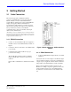
Service Monitor User Manual 3 Getting Started 3.1 Cable Connection The monitoring program communicates with the compressor via the Modbus* protocol using either the RS232 or RS485 connection at the Chiller Interface module. RS485 communication requires an RS485/RS232 adapter (user-supplied). RS232 communication is recommended for cable lengths not exceeding 15 meters (50 feet) between the PC and compressor. For cables that run up to 100 meters (328 feet), use the RS485 communication line.
Getting Started Figure 2 PC to Modbus Connection (single compressor with > 10 m cable length) Figure 3 PC to Modbus Connection (multiple compressors with > 10 m cable length) 4 Danfoss Turbocor Compressors Inc. ECD-00007M Rev.
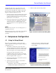
Service Monitor User Manual 3.2 Monitor Program Installation The monitor program is installed on the PC and communicates with the compressor using the ModBus protocol over a RS-232 or RS-485 serial link. Administrator privileges may be required to install and remove software on the PC. Installation Procedure: 1. Insert the monitor program CD into the drive. 2. In Windows Explorer, navigate to the Turbocor_Service_Tool_Setup.msi file. Double-click the file to launch the setup wizard. 3.
Getting Started Table 2 Monitor Program Toolbar Icons (Continued) Icon Name Expansion Valves Event Log EEPROM Settings Load Profile Graphs Fault Captures Trending Chiller Control Compressor Envelope Description Clicking on the “Expansion Valves” icon opens the “Electronic Valve / Data Tuning” window. Refer to section 6.6 "Electronic Valve Data / Tuning" on page 33. Clicking on the “Event Log” icon opens the “Compressor Event Log” window. Refer to section 6.10 "Compressor Event Log" on page 51.
Service Monitor User Manual Access Code - The access code controls access to all adjustable parameters. The default user access level on power up is read only. Enter the code that corresponds to the access level you require. Contact Turbocor Product Support to obtain the required access code. 1. Once the serial port connection data has been set, click the Connect button. At this point, connection status, compressor details, and user access level appear in the right-hand pane of the dialog box. 2.
Compressor Configuration • Modbus Network: the compressor receives a demand from an external computer, PLC, or building management system using the Modbus protocol on a RS-232 or RS-485 communication link. • Chiller Control: fully automatic; controls the chilled water temperature using a temperature sensor connected directly to the Chiller Interface module. This mode can also be used to control evaporating temperature which is derived from the suction pressure measurement 6.
Service Monitor User Manual This section explains how to set up the expansion valves for various applications. Both valves can be operated independently or in parallel. For Expansion Valve #1: 1. Enter the number of steps to drive the valve from fully closed to fully open. Expansion valves with different numbers of steps can be used.
Compressor Configuration 5. 6. process error and replaces the PID controller gains (proportional, integral, and derivative). to hold the number of steps sent to the motor as determined by the Starting Valve Position %. Value is in seconds and starts to count down when the drive is enabled. 7. Enter the Control Setpoint, i.e., suction superheat or liquid level. (Not applicable to load balance control mode.) Enter the Minimum Closure During Operation.
Service Monitor User Manual 4.1.3 Analog Output Setup The compressor features a universal analog output for load balancing valve, IGV position, discharge pressure, etc. The operating range can be set to 0-5V or 0-10V via jumpers on the Chiller Interface module. module is connected to a 3-way valve that channels chilled water to a cooling coil. A temperature sensor at the cooling coil is connected to the Leave terminals of the Chiller Interface module.
Compressor Configuration Figure 11 Analog Output Setup 2. 3. 4. Enter the Starting Output. This value equals the percentage of maximum voltage sent to the terminals of the Chiller Interface module on compressor start-up. The analog output will hold at this position until the start delay timer has expired. Enter Starting Output Delay Time. This value is the amount of time from compressor start-up to hold the voltage at the start-up %.
Service Monitor User Manual 1. 2. Turn OFF power to the compressor. Wait at least 5 minutes, then check that the LEDs on the Backplane are OFF. Turn ON power to the compressor. IMPORTANT: Record the comm settings before you close the monitor program since they will be necessary to communicate with the compressor when you restart the monitor program. 3. 4.2 Close and then restart the Monitor program.
Compressor Configuration 4.3 Controlling User Access The access code system allows OEM customers to set their own unique pass codes thereby restricting access to company authorized personnel. These access codes control access to all adjustable parameters via the Modbus communications layer. The access levels are: • Read only ~ User may only view values across the Modbus layer. • Low Level ~ User may only alter basic settings such as leaving chilled water temp, display units, chiller enable/ disable, etc.
Service Monitor User Manual 5 Starting and Stopping the Compressor The following sections describes how to start and stop the compressor. Refer to the section corresponding to the 5.1 Analog Input The Analog Input mode controls the compressor loading using an analog demand signal of 0-10 VDC from an external controller. The variable demand signal corresponds to the range of 0-100% maximum power available.
Starting and Stopping the Compressor 5.2.2 How to Stop the Compressor To stop the compressor, enter ‘0’ in the Loading Demand field. Figure 17 Compressor Control Form 5.3 Chiller Control The Chiller Control mode is fully automatic and controls the chilled water temperature using a temperature sensor connected directly to the Chiller Interface module.
Service Monitor User Manual Figure 18 Chiller Control Form Danfoss Turbocor Compressors Inc. ECD-00007M Rev.
Monitor Program Data and Controls 6 Monitor Program Data and Controls This section provides a detailed description of the forms and related data and controls that are accessible via the monitor program’s user interface.
Service Monitor User Manual Figure 19 General Data Page Table 4 General Data Page Parameters Parameter Description Ts [sat] Tc [sat] 3 Phase Power In Shaft Speed Compressor Demand Saturated suction temperature Saturated discharge temperature 3-phase AC input power (mains input) Actual shaft speed in RPM Requested motor power demand as a percentage of maximum motor power [kW]. The actual discharge gauge pressure at the compressor flange as measured by the suction pressure transducer.
Monitor Program Data and Controls 6.2 Bearing Calibration The “Calibration Data” window allows the user to view and compare the data of the latest calibration performed with the latest stored calibration data, thus allowing the user to verify that the bearing calibration was performed successfully. It also allows the user to perform a manual bearing calibration. NOTE: Bearing calibration is always automatically performed during compressor startup.
Service Monitor User Manual Table 5 Calibration Data Details Data Parameter FRY Max BRX Min BRX Max BRY Min BRY Max Ax Min Ax Max FRX Gain FRX Offset FRX HW Offset FRY Gain FRY Offset FRY HW Offset BRX Gain BRX Offset BRX HW Offset BRY Gain BRY Offset BRY HW Offset Ax Gain Ax Offset Ax HW Offset Time Stamp Description Maximum DC voltage indicating maximum front radial y displacement. Minimum DC voltage indicating minimum rear radial x displacement.
Monitor Program Data and Controls 6.2.1 Bearing Calibration Procedure For the bearing calibration to be performed: • The shaft must be de-levitated • The interlock connection on the Chiller Interface module must be open 1. Turn OFF the AC input power to the compressor and wait 3-5 minutes for the capacitors to discharge. 2. Turn ON the AC input power to the compressor. 3. Launch the monitor program. If the monitor program is already running, close it and open it again. 4.
Service Monitor User Manual the “Latest Check” and the “Stored Calibration”; see 6.2.2 "Calibration Data Interpretation": • - FRX Gain - FRY Gain - BRX Gain - BRY Gain - AX Gain Interpretation: Bearing calibration was successful.
Monitor Program Data and Controls Figure 24 Compressor Controller Form 24 Danfoss Turbocor Compressors Inc. ECD-00007M Rev.
Service Monitor User Manual Table 6 Compressor Controller Parameters Parameter Description Te (on title bar) Tc (on title bar) SH (on title bar) Evaporation Temperature Condensation Temperature Superheat Calculation [Metric: ºK; Imperial: ºR] If the absolute superheat value is < 5, then the gas is wet and will cause the motor to overwork (as wet gas is heavier than dry gas). Critical Faults Displays the compressor’s most recent active critical fault. Refer to 6.3.
Monitor Program Data and Controls Table 6 Compressor Controller Parameters (Continued) Parameter Description Total Compression Ratio Ratio of the absolute discharge pressure and the absolute suction pressure. Estimated minimum RPM the compressor can run at with a fully open inlet guide vane. Maximum RPM the compressor can run at for a given set of inlet and outlet conditions.
Service Monitor User Manual temperature which is derived from the suction pressure measurement. NOTE: In Manual Control mode, the Chiller Interface interlock switch has no effect on the compressor state. NOTE: The Chiller Interface interlock switch must be closed and no errors present for the compressor to start up and run. Analog Input The Analog Input mode controls the compressor loading using an analog demand signal of 0-10 VDC from an external controller.
Monitor Program Data and Controls Table 7 Compressor Faults and Alarms (Continued) Fault / Alarm Possible Cause 3-Phase Over-Current Fault / Alarm Excessive system load (usually due to compressor pumping liquid). Note: A “3 Phase Over Current” fault will lock out the compressor. The compressor will have to be powered down and restarted. Insufficient motor cooling Insufficient water flow. Faulty condenser or insufficient load on the evaporator.
Service Monitor User Manual Figure 25 Motor Monitoring Form Table 8 Motor Monitoring Parameters Parameter General Motor Data: Actual Shaft Speed (RPM) Desired Shaft Speed (RPM) Inverter Side Motor Amps = Id Inverter Side Motor Amps = Iq Earth Leakage Current Calculated Total Power Requested Motor Power Inverter Temperature Back EMF Value Fault Code Alarm Code Danfoss Turbocor Compressors Inc. ECD-00007M Rev. 1 Description Actual shaft speed in RPM.
Monitor Program Data and Controls Table 8 Motor Monitoring Parameters (Continued) Parameter Description Fault Text Box Displays the motor’s most recent active fault. Refer to 6.4.2 "Motor Faults / Alarms" for alarm details. Displays the motor’s most recent active alarm. Refer to 6.4.2 "Motor Faults / Alarms" for fault details.
Service Monitor User Manual NOTE: A motor alarm will slow down the motor, whereas a motor fault will trip the motor. Table 9 Motor Faults and Alarms Fault / Alarm Possible Cause Motor Single Phase Over-Current Detected DC Bus Over-Voltage Detected Motor High Current Warning Excess liquid at the suction valve, thus causing the motor to overwork and generate too much current. DC bus voltage exceeds acceptable voltage range.
Monitor Program Data and Controls Figure 26 Magnetic Bearing Monitoring Form Table 10 Bearing Monitoring Parameters Parameter Description Shaft Levitation State Shaft state control.
Service Monitor User Manual Table 10 Bearing Monitoring Parameters (Continued) Parameter Description Alarm Code Fault Text Box Hexadecimal bearing alarm code from the bearing motor control. Displays the most recent active bearing fault. Refer to 6.5.2 "Bearing Faults" for fault details. Graphical representation of the front radial orbit of the shaft. Graph Percentile shown at the bottom right-hand corner indicates the average front orbit displacement.
Monitor Program Data and Controls Chiller Interface module. Similarly, the “EXV#2 Control Settings” controls the stepper motor connected to “EXV2” on the Chiller Interface module. Table 12 describes the stepper motor control parameters. To access the analog output controls, select the “Analogue Output” tab. The “Analog Output Controls” controls the output labeled “Analog” on the Chiller Interface module. Table 13 describes the analog output control parameters. the measurement unit, refer to section 6.
Service Monitor User Manual Table 12 Electronic Valve Data / Tuning Parameters (Stepper Motors) Parameter Description Control Mode Selects which control variable will be maintained by the stepper motor output. The options are: 1. Superheat control using the compressor flange temperature and pressure (this mode is not recommended as the temperature at the compressor flange is influenced by external factors). 2.
Monitor Program Data and Controls Table 13 Electronic Valve Data / Tuning Parameters (Analog Output) Parameter Description Control Mode Selects which control variable will be maintained by the 0 -10 VDC output labeled “ANALOG” on the Chiller Interface module.
Service Monitor User Manual To view the “Chiller Control” window, select “Window”→ “Chiller Control” from the menu bar, or click on the “Chiller Control” icon located below the menu bar. Table 14 provides details about the chiller controller parameters. NOTE: IMPORTANT: To change a parameter setting, double-click the variable field, scroll or type in the new setting, and press Enter. It is important to press Enter as this causes the user input to be validated.
Monitor Program Data and Controls Table 14 Chiller Controller Parameters Parameter Description Chiller Control Mode Selection of the sensor that the chiller control will try to maintain the value of. The options are: • Leaving Chiller Water: Controls the water or air temperature leaving the chiller. • Entering Chiller Water: Controls water or air temperature entering the chiller. • Evaporating Temperature: Controls the evaporating (saturated suction) temperature.
Service Monitor User Manual Figure 29 System Information 6.8.1 Compressor Info 6.8.2 EEPROM Log Resets Selecting the “Compressor Info” tab allows the user to view the system information. Specifically, it allows the user to view the: Selecting the “Eeprom Log Resets” tab allows the user to: • Compressor model and serial # • BMC PCB hardware serial # • Software revision installed • Configuration version Click on the “Request System Information” button to obtain the system information. 6.
Monitor Program Data and Controls 6.9.1 Compressor Controller Settings Select the “CC_Control” tab to view the following: • Monitor program measurement unit selected • Chiller Control Parameters • Compressor Startup Parameters The compressor controller parameters are described in Table 15.
Service Monitor User Manual Table 15 EEPROM Settings - Compressor Controller Parameters (Continued) Parameter Description Control Mode Displays the sensor that the chiller control will try to maintain the value of. The options are: • Leaving Chiller Water: Controls the water or air temperature leaving the chiller. • Entering Chiller Water: Controls water or air temperature entering the chiller. • Evaporating Temperature: Controls the evaporating (saturated suction) temperature.
Monitor Program Data and Controls Figure 31 EEPROM Settings - Compressor Controller Alarm Limits Table 16 EEPROM Settings - Compressor Controller Alarm Limit Parameters Parameter Description Discharge Pressure The actual discharge gauge pressure at the compressor flange as measured by the discharge pressure transducer. Inverter temperature as measured by thermistor mounted under the IGBT Inverter.
Service Monitor User Manual 6.9.3 Compressor Controller Fault Limits Select the “CC Trip Limits” tab to view the compressor general fault limits. Table 17 describes the general trip limits. The limits represent the maximum temperature and/or pressure values the compressor will tolerate before activating a fault.
Monitor Program Data and Controls Table 17 EEPROM Settings - Compressor Controller Fault Limit Parameters Parameter Description Discharge Pressure The actual discharge gauge pressure at the compressor flange as measured by the discharge pressure transducer. Inverter temperature as measured by thermistor mounted under the IGBT Inverter. The actual discharge temperature at the compressor flange as measured by the discharge temperature/pressure transducer.
Service Monitor User Manual Figure 33 EEPROM Settings - Stepper Motor Settings 6.9.5 Stepper Motor Valve Controls Select the “EXV#1 Settings” tab to view the control settings for the electronic expansion valve #1 (EXV#1). EXV#1 refers to the electronic expansion valve connected to “EXV1” at the Chiller Interface module. Similarly, select the “EXV#2 Settings” tab to view the control settings for the electronic expansion valve #2 (EXV#2).
Monitor Program Data and Controls Figure 34 EEPROM Settings - Stepper Motor Valve #1 Controls 46 Danfoss Turbocor Compressors Inc. ECD-00007M Rev.
Service Monitor User Manual Table 18 EEPROM Settings - EXV Parameters Parameter Description Control Mode Displays which control variable will be maintained by the stepper motor output. The options are: 1. Superheat control using the compressor flange temperature and pressure (this mode is not recommended as the temperature at the compressor flange is influenced by external factors). 2.
Monitor Program Data and Controls . Figure 35 EEPROM Settings - Analog Output Controls 48 Danfoss Turbocor Compressors Inc. ECD-00007M Rev.
Service Monitor User Manual Table 19 Electronic Valve Data / Tuning Parameters (Analog Output) Parameter Description Analog Control Mode Selects which control variable will be maintained by the 0-10VDC output labeled “ANALOG” on the Chiller Interface module.
Monitor Program Data and Controls Figure 36 EEPROM Settings - Compressor Controller Impeller Specific Settings 6.9.8 Compressor Controller (CC) Critical Fault Lock Outs • Inverter temperature alarm Select the “CC LockOuts” tab to view the setup for the CC critical fault lock outs.
Service Monitor User Manual Figure 37 EEPROM Settings - CC Critical Fault Lock Outs 6.9.9 Refrigerant TBD 6.10 Compressor Event Log The compressor event log provides the user with details about the compressor events and faults. To view the “Compressor Event Log” window, select “Window”→ “Event Log” from the menu bar, or click on the “Event Log” icon located below the menu bar.
Monitor Program Data and Controls Fault” parameter box indicates the current event being displayed. Figure 38 Event Log Window 6.11 History Data The “Compressor History Data” window provides the user with information about the compressor energy usage. 52 To view the “Compressor History Data” window, select “Window”→ “Load Profile” from the menu bar, or click on the “Load Profile Graphs” icon located below the menu bar. Danfoss Turbocor Compressors Inc. ECD-00007M Rev.
Service Monitor User Manual Figure 39 Compressor History Data Table 20 Compressor History Data Parameters Parameter Description Graph: %Power Demand vs. Hours The graph shows the number of hours the compressor has been in operation for a given power demand. The statistical values of operating hours for each 10% of power demand is displayed in the “Load Profile Data” section. Total time the compressor has been running. The estimated total energy used in an hour.
Monitor Program Data and Controls down menu. All graphs may be cleared simultaneously by clicking on “Reset Graphs” located on the menu bar. When the “Graphs” window is closed, all parameters selected for graphing are automatically saved to a .csv data file, and may be viewed using a spreadsheet editor such as Microsoft® Excel. Each data file is limited by a maximum file size of 32,768 (215) lines of data. The data file is named “Turbocor Service Monitoring Software#.
Service Monitor User Manual Table 21 Trending Parameters (Continued) Parameter Discharge Pressure Suction Temperature Discharge Temperature Cavity Temperature Entering Air/Water Temp Leaving Air/Water Temp 24VDC Supply InterLock Status Surge Speed Choke Speed Stepper #1 PV Stepper #1 Position Stepper #2 PV Stepper #2 Position Cooling Solenoid Status Axial Force FX Force FY Force BX Force BY Force Actual Speed Desired Speed Motor Amps (Inverter Side) 3 Phase Power (kW) Inverter Temperature Front Orbit A
Monitor Program Data and Controls 6.12.
Service Monitor User Manual For each parameter, check the checkbox next to the parameter to plot the parameter. Uncheck the checkbox to stop plotting the parameter. To clear the graphs, click on the “Clear Graphs” button. To the right of the graphs, the compressor event log is displayed. However, the only events shown are those that occur after the “Trending & Data Acquisition” window is opened. To clear the event log, click on the “Clear Event Log” button.
Monitor Program Data and Controls The graph, as shown in Figure 43, displays the saturated discharge temperature (SDT) versus the evaporator capacity. For a given evaporator capacity, the red lines mapped on the graph represents the constant compressor speed (in RPM) required to bring the saturated discharge temperature to the desired level.
Service Monitor User Manual Figure 44 Compressor Map Window 6.14 Fault Captures The “Fault Captures” window allows the user to view all the compressor faults, and the state of the compressor at the time the fault occurred. To view the “Fault Captures” window, select “Window”→ “Fault Captures” from the menu bar, or click on the “Fault Captures” icon located below the menu bar. Click on the “Download All Faults” button. A list of the most recent faults will be shown below the button.
Monitor Program Data and Controls Figure 45 Stored Faults Window 6.15 Data Capture The “Compressor Data Capture Screen” allows the user to view the compressor data, listed in Table 22, at a particular instant in time. To capture the data, click on “Capture Data” from the menu bar. An “Acquiring Data” message box appears. After the “Acquiring Data” message box disappears, click on the “Data Preview” button to view the compressor data.
Service Monitor User Manual Figure 46 Compressor Data Capture Screen Danfoss Turbocor Compressors Inc. ECD-00007M Rev.
Monitor Program Data and Controls Table 22 List of Compressor Data Captured Data Parameter 0 Compressor Control Faults 1 Compressor Control Alarms 2 Compressor Control Mode 3 Compressor Demand % 4 Inlet Guide Vane % Open 5 Suction Pressure 6 Discharge Pressure 7 Suction Temperature 8 Discharge Temperature 9 10 11 12 13 Cavity Temperature Controller PCB Temperature Backplane Temperature Stepper PCB Temperature Entering Water Temperature 14 Leaving Water Temperature 15 17 18 19 20 Est
Service Monitor User Manual Table 22 List of Compressor Data Captured (Continued) Data Parameter 24 25 26 Actual Shaft Speed (RPM) Desired Shaft Speed (RPM) Inverter Side Motor Amps 27 28 29 Earth Leakage Current 3-Phase Power Input Inverter Temperature 30 31 32 33 34 35 36 37 38 39 40 41 42 Back EMF Shaft Status Ax Un-balance % Fr Un-balance % Br Un-balance % Ax Force [Amps] Fx Force [Amps] Fy Force [Amps] Bx Force [Amps] By Force [Amps] 3 Phase Amps 3 Phase Voltage Compressor Real Time Clock Danfos
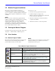
Service Monitor User Manual Appendix A: Determination of Actual Power Setting The BMC\CC holds four variables in the EPROM that determine the input power capability of the compressor based on the model number of the compressor. These four variables define the straight-line equation for the maximum referred power (y=mx+c) as a function of total flange to flange pressure ratio, see graph below. The referred power is the power absorbed at the reference pressure and temperature.
For a reference pressure of 356kPa at 283ºK: The referred power is determined to be: PWRref = 24.783*2.80-14.06 = 55.32 kW The actual maximum power is: PWRmax= 55.32 * (340 / 356) = 52.83 kW The desired 3 phase power input is then : Desired power = 52.83 * .562 = 29.69 kW A-2 Danfoss Turbocor Compressors Inc. ECD-00007M Rev.