
User manual

Service Monitor User Manual
Danfoss Turbocor Compressors Inc. 29
ECD-00007M Rev. 1
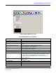
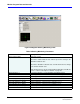
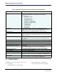
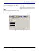
Figure 25 Motor Monitoring Form
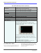
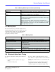
Table 8 Motor Monitoring Parameters
Parameter Description
General Motor Data:
Actual Shaft Speed (RPM) Actual shaft speed in RPM.
Desired Shaft Speed (RPM) Commanding shaft speed in RPM (always higher than the actual shaft
speed).
Inverter Side Motor Amps = Id Current output from the IGBT Inverter to the motor.
Torque-generating current component.
Inverter Side Motor Amps = Iq Current output from the IGBT Inverter to the motor.
Flux-generating current component.
Earth Leakage Current Motor current that leaks to ground due to an insulation fault.
Calculated Total Power Calculated 3-phase input power in kW.
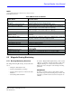
Requested Motor Power Requested motor power in kW. Value is a function of the compressor
model designation and demand percentage. The demand percentage
is set through the “Loading Demand (% max power)” in the
“Compressor Controller” window. Refer to section 6.3 "Compressor
Control" on page 23.
Inverter Temperature Inverter temperature as measured by thermistor mounted under the
IGBT Inverter.
Back EMF Value Internal motor voltage
Fault Code Hexadecimal motor fault code from the bearing motor control.
Alarm Code Hexadecimal motor alarm code from the bearing motor control.