VLT® 2800 Series ■ Contents Quick Setup ....................................................................................................... General warning ..................................................................................................... Mechanical Installation ........................................................................................... Electrical Installation, power ...................................................................................
VLT® 2800 Series Electrical installation, control terminals ................................................................... Relay connection ................................................................................................... VLT Software Dialog .............................................................................................. Connection examples ............................................................................................ All about VLT 2800 ..................
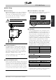
VLT® 2800 Series ■ Quick Setup ■ General warning Using this Quick Setup, you can carry out quick and EMC-correct installation of the frequency converter in five steps. The Operating Instructions, which are also enclosed, give other examples of installation and describe all functions in detail. ■ Electrical Installation, control cables Remove the front cover underneath the control panel. Place a jumper between terminals 12 and 27.
VLT® 2800 Series operation [0], i.e. via the control terminals, or Local [1], i.e. via the control unit. Set the control location to Local [1]. Local/remote operation = Local [1] Par. 002 Set the motor speed by adjusting the Local reference Local reference Parameter 003 ■ Safety regulations The voltage of the frequency converter can be fatal whenever it is connected to mains.
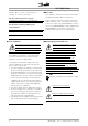
VLT 2800 Series 195NA009.17 VLT® 2800 Series Introduction to VLT 2800 Operating instructions Software version: 2.8x These operating instructions can be used for all VLT 2800 Series frequency converters with software version 2.8x. The software version number can be seen from parameter 640 Software version no. MG.28.A9.
VLT® 2800 Series Warning: It can be extremely dangerous to touch the electrical parts even when the mains supply has been disconnected. Also ensure that other voltage inputs are disconnected from load sharing through the DC bus. Wait at least 4 minutes after the input power has been removed before servicing the drive. 195NA139.10 6 MG.28.A9.
VLT® 2800 Series The voltage of the frequency converter is dangerous whenever the converter is connected to mains. Incorrect fitting of the motor or frequency converter may cause damage to the equipment, serious injury or death. Consequently, it is essential to comply with the instructions in this manual as well as local and national rules and safety regulations. ensure that no unintended start occurs, these stop functions are not sufficient. 2. While parameters are being changed, the motor may start.
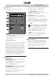
VLT® 2800 Series ■ Control unit On the front of the frequency converter there is a control panel. These keys are also used in Display mode for selecting the display of an operating value. The [QUICK MENU] + [+] keys must be pressed at the same time to give access to all parameters. See Menu mode. [STOP/RESET] is used for stopping the connected motor or for resetting the frequency converter after a trip. Can be selected as Active [1] or Not active [0] via parameter 014 Local stop/reset.
VLT® 2800 Series ■ Display readout states Display mode The display shows that in parameter 128 Motor thermal protection the selection made is Thermistor trip [2]. Menu mode In order to enter the Menu mode [QUICK MENU] + [+] must be activated at the same time. In Menu mode, most of the frequency converter parameters can be changed. Scroll through the parameters using the [+/-] keys. While scrolling in the Menu mode proceeds, the parameter number will flash.
VLT® 2800 Series On the control terminals, the following control signals will remain active when Hand mode is activated: • Hand Start (LCP2) • Off Stop (LCP2) • Auto Start (LCP2) • Reset • Coasting Stop Inverse • Reset and Coasting Stop Inverse • Quick Stop Inverse • Stop Inverse • Reversing • DC Braking Inverse • Setup Select LSB • Setup Select MSB • Thermistor • Precise Stop Inverse • Precise Stop/Start • Jog • Stop Command Via Serial Comm. 3.
VLT® 2800 Series ■ Operation & Display 001 Language (LANGUAGE) Value: ✭English (ENGLISH) German (DEUTSCH) French (FRANCAIS) Danish (DANSK) Spanish (ESPANOL) Italian (ITALIANO) [0] [1] [2] [3] [4] [5] Function: This parameter is used to choose the language to be shown in the display whenever the LCP control unit is connected. is set at Local control and open loop [1] or Local control as parameter 100 [3]. Parameter 200 Output frequency range is set at Both directions. 4.
VLT® 2800 Series Description of choice: Copy to all Setups from # (COPY TO ALL) Factory Setup [0] contains the factory-set parameter values. Setup 1-4 [1]-[4] are four individual Setups which can be selected as required. Multi Setup [5] is used where remote-controlled shifts between the four Setups via a digital input or via serial communication is required. [5] Function: You can copy from the selected active Setup in parameter 005 Programming setup to the selected Setup or Setups in this parameter.
VLT® 2800 Series 008 Display scaling of output frequency (FREQUENCY SCALE) Value: 0.01 - 100.00 ✭ 1.00 Function: In this parameter, the factor is selected by which the output frequency is to be multiplied. The value is shown in the display, provided parameters 009-012 Display readout have been set to Output frequency x scaling [5]. (HEATSINK TEMP [°C]) Alarm word [Hex] (ALARM WORD [HEX]) Control word [Hex] (CONTROL WORD [HEX]) Warning word [Hex] (WARNING WORD [HEX]) Extended status word [Hex] (EXT.
VLT® 2800 Series DC link voltage [V] gives the intermediate circuit voltage of the frequency converter. Thermal load motor [%] gives the calculated/estimated load on the motor. 100 % is the cut-out limit. Thermal load [%] gives the calculated/estimated thermal load on the frequency converter. 100 % is the cut-out limit. Running hours [Hours] gives the number of hours that the motor has tun since the last reset in parameter 619 Reset of running hours counter.
VLT® 2800 Series Description of choice: and open loop [1]: The present motor frequency and direction of rotation will be maintained. If the present direction of rotation does not respond to the reversing signal (negative reference), the reference will be set to 0. See parameter 009 Large display readout. 013 Local control (LOC CTRL/CONFIG.
VLT® 2800 Series Description of choice: Description of choice: If Not active [0] is selected in this parameter, the [JOG]-key will be inactive. If Locked [1] is selected, data changes in the parameters cannot be made; however, it will still be possible to make data changes via serial communication. Parameter 009-012 Display readout can be changed via the control panel.
VLT® 2800 Series 020 Hand operation NB!: Please note that this parameter can only be set using an LCP 2 control panel. See Order form. Value: ✭Not active (DISABLE) Active (ENABLE) [0] [1] Function: In this parameter you can select whether it should be possible or not to switch between Auto- and Hand mode. In Auto mode the frequency converter is controlled by external signals whereas the frequency converter in Hand mode is controlled via a local reference directly from the control unit.
VLT® 2800 Series ■ Load and Motor 100 Configuration (CONFIGURATION) Value: ✭Speed control, open loop (SPEED OPEN LOOP) Speed control, closed loop (SPEED CLOSED LOOP) Process control, closed loop (PROCESS CLOSED LOOP) [0] [1] Variable torque high (TORQUE: HIGH) Variable torque low with CT start (VT LOW CT START) Variable torque medium with CT start (VT MED CT START) Variable torque high with CT start (VT HIGH CT START) Special motor mode (SPECIAL MOTOR MODE) [4] [5] [6] [7] [8] [3] CT = Constant torque
VLT® 2800 Series NB!: Please note that if a value set in the nameplate parameters 102-106 is changed, there will be an automatic change of parameter 108 Stator resistance and 109 Stator reactance. (MOTOR CURRENT) Value: 0,01 - IMAX ✭ Depends on choice of motor Function: The nominal, rated current of the motor IM,N forms part of the frequency converter calculation of features such as torque and motor thermal protection. 102 Motor power PM,N (MOTOR POWER) Value: 0.
VLT® 2800 Series the frequency converter to the motor being used. This is used in particular when the factory setting does not sufficiently cover the motor. For the best possible tuning of the frequency converter it is recommended that AMT is performed on a cold motor. It should be noted that repeated AMT runs can cause heating of the motor, resulting in an increase in the stator resistance RS. As a rule, however, this is not critical. AMT is performed as follows: Start AMT: 1. Give a STOP signal. 2.
VLT® 2800 Series 2. The value is obtained through manual measurements XS is obtained by connecting a motor to mains and measuring the phase-phase voltage U M and the idle current . XL: See parameter 142. 3. Use the factory settings of XS which the frequency converter itself chooses on the basis of the motor nameplate data. If the active motor current is below 10%, the motor voltage will be decreased by the speed mentioned above until the voltage reaches the setting for Par. 117.
VLT® 2800 Series 121 Start function (START FUNCTION) Value: DC hold during start delay time (DC HOLD/DELAY TIME) DC brake during start delay time (DC BRAKE/DELAY TIME) ✭Coasting during start delay time (COAST/DELAY TIME) Start frequency/voltage clockwise (CLOCKWISE OPERATION) Start frequency/voltage in reference direction (VERTICAL OPERATION) [0] voltage will equal parameter 131 Voltage at start. This functionality is used typically for hoist applications with counterweight.
VLT® 2800 Series NB!: If parameter 123 is set too high, and DC hold has been chosen in parameter 122, the output frequency will jump to the value in parameter 123 without ramping up. This may cause an overcurrent warning / alarm. Function: The frequency converter can monitor the motor temperature in two different ways: - - 126 DC brake time (DC BRAKING TIME) Value: 0 - 60 sec. ✭ 10 sec Function: In this parameter, the DC brake time is set at which parameter 132 DC brake voltage is to be active.
VLT® 2800 Series 130 Start frequency 132 DC brake voltage (START FREQUENCY) Value: 0.0 - 10.0 Hz (DC BRAKE VOLTAGE) ✭ 0.0 Hz Function: The start frequency is active for the time set in parameter 120 Start delay, after a start command. The output frequency will ’jump’ to the next preset frequency. Certain motors, such as conical anchor motors, need an extra voltage/start frequency (boost) at start to disengage the mechanical brake.
VLT® 2800 Series 134 Load compensation 136 Slip compensation (LOAD COMPENSATIO) Value: 0.0 - 300.0% (SLIP COMP.) ✭ 100.0% Value: -500 - +500% of rated slip compensation ✭ 100% Function: In this parameter, the load characteristic is set. By increasing the load compensation, the motor is given an extra voltage and frequency supplement at increasing loads. This is used e.g. in motors/applications in which there is a big difference between the full-load current and idle-load current of the motor.
VLT® 2800 Series 139 Brake cut in frequency (BRAKE CUT IN) Value: 0.5 - 132.0/1000.0 Hz ✭ 3.0 Hz Function: Here you can select the frequency at which the external brake is activated; this takes place via the output defined in parameter 323 Relay output 1-3 or 341 Digital output terminal 46. Description of choice: Set the required frequency.
VLT® 2800 Series NB!: If the value in par. 144 is increased, the motor current will simultaneously increase significantly when generator loads are applied. The parameter should therefore only be changed if it is guaranteed during measurement that the motor current in all operating situations will never exceed the maximum permitted current in the motor. Please note: that the current cannot be read out from the display.
VLT® 2800 Series ■ References & Limits 201 Output frequency low limit, fMIN (MIN OUTPUT FREQ) 200 Output frequency range Value: 0.0 - fMAX (OUT FREQ. RNG/ROT) Value: ✭Only clockwise, 0 - 132 Hz (132 HZ CLOCKWISE) Both directions, 0 - 132 Hz (132 HZ BOTH DIRECT) Anti-clockwise only, 0 - 132 Hz (132 HZ COUNTER CLOCK) Clockwise only, 0 - 1000 Hz (1000 HZ CLOCK WISE) Both directions, 0 - 1000 Hz (1000 HZ BOTH DIRECT) Anti-clockwise only, 0 - 1000 Hz (1000 HZ COUNTER CLOCK) [0] [1] [2] ✭ 0.
VLT® 2800 Series closed loop. You should select Min ref. - Max. ref. [0], if Process regulation, closed loop [3] has been selected in parameter 100 Configuration. Description of choice: Select the required range. 204 Minimum reference, Ref MIN The reference unit can be defined from the following table: Value: Par. 100 Config. = Open loop [0]. -100,000.000 - par. 205 RefMAX ✭ 0.000 Hz Par. 100 Config. = Closed loop [1]/[3]. -Par. 414 Minimum feedback - par. 205 RefMAX ✭ 0.
VLT® 2800 Series 207 Ramp-up time 1 (RAMP-UP TIME 1) Value: 0.02 - 3600.00 sec Description of choice: Set the required ramp-up time. Shift from ramp 1 to ramp 2 by activating Ramp 2 via a digital input. ✭ 3.00 sec (VLT 2803-2875) 10.00 sec (VLT 2880-2882) Function: The ramp-up time is the acceleration time from 0 Hz to the rated motor frequency fM,N (parameter 104 Motor frequency, fM,N). It is assumed that the output current will not reach the current limit (set in parameter 221 Current limit ILIM).
VLT® 2800 Series 212 Quick-stop ramp-down time Description of choice: (Q STOP RAMP TIME) Value: 0.02 - 3600.00 sec. ✭ 3.00 sec (VLT 2803-2875) 10.00 sec (VLT 2880-2882) Function: The quick-stop ramp-down time is the deceleration time from the rated motor frequency to 0 Hz, provided no overvoltage arises in the inverter because of generating operation of the motor, or if the generated current exceeds the current limit in parameter 221 Current limit ILIM.
VLT® 2800 Series 219 Catch up/ Slow down reference (CATCH UP/SLW DWN) Value: 0.00 - 100% of the given reference ✭ 0.00% Function: In this parameter, the percentage value can be set which will either be added to or deducted from the remote-controlled references. The remote-controlled reference is the sum of preset references, analogue references, pulse reference and any references from serial communication.
VLT® 2800 Series 225 Warning: Low frequency, fLOW 227 Warning: Low feedback, FBLOW (WARN.FREQ. LOW) Value: 0.0 - par. 226 Warn.: High frequency, fHIGH (WARN.FEEDB. LOW) Value: -100,000.000 - par. 228 Warn.:FBHIGH✭ -4000.000 ✭ 0.0 Hz Function: If the output frequency falls below the preset limit fLOW, a warning is given. Parameters 223-228 Warning functions are out of function during ramp-up after a start command and after stop command or during stop.
VLT® 2800 Series 229 Frequence bypass, bandwidth (FREQ BYPASS B.W.) Value: 0 (OFF) - 100 Hz ✭ 0 Hz Function: Some systems call for some output frequencies to be avoided because of mechanical resonance problems in the system. In parameters 230-231 Frequency bypass these output frequencies can be programmed. In this parameter a bandwidth can be defined on either side of these frequencies.
VLT® 2800 Series Digital inputs Value: No function Reset Coasting stop inverse Reset and coasting inverse Quick-stop inverse DC braking inverse Stop inverse Start Pulse start Reversing Reversing and start Start clockwise Start anti-clockwise Jog Freeze reference Freeze output frequency Speed up Speed down Catch-up Slow-down Ramp 2 Preset ref, LSB Preset ref, MSB Preset reference on Thermistor Precise stop, inverse Precise start/stop Pulse reference Pulse feedback Pulse input Selection of Setup, lsb Selecti
VLT® 2800 Series Function: In these parameters 302-307 Digital inputs it is possible to choose between the different enabled functions related to the digital inputs (terminals 18-33). Description of choice: No operation is selected if the frequency converter is not to react to signals transmitted to the terminal. Reset resets the frequency converter after an alarm; however, a few alarms cannot be reset (trip locked) without first disconnecting the mains supply and reconnecting it.
VLT® 2800 Series NB!: If Freeze output is active the frequency converter can only be stopped if you select Motor coast, Quick stop or DC braking via a digital input. Speed up and Speed down are selected if digital control of the up/down speed is required. This function is only active if Freeze reference or Freeze output frequency has been selected. If Speed up is active the reference or output frequency will be increased, and if Speed down is active the reference or output frequency will be reduced.
VLT® 2800 Series 327 Pulse reference/feedback the maximum pulse feedback frequency is set. If this function is chosen, see Wobble Instruction MI28JXYY for further information. Pulse input is selected if a specific number of pulses must lead to a Precise stop, see parameter 343 Precise stop and parameter 344 Counter value. 309 Terminal 53 Min. scaling (AI 53 SCALE LOW) Selection of Setup, lsb and Selection of Setup, msb gives the possibility to select one of the four setups.
VLT® 2800 Series 315 Terminal 60, min. scaling and parameter 316 Terminal 60, max. scaling. Description of choice: Set the required current value. Description of choice: No function [0]. Is selected if the frequency converter is not to react to signals connected to the terminal. Reference [1]. If this function is selected, the reference can be changed by means of an analogue reference signal. If reference signals are connected to more than one input, these reference signals must be added up.
VLT® 2800 Series - An output signal is obtained, which is proportional to the feedback value in the interval Minimum feedback, FBMIN - Maximum feedback, FBMAX (parameter 414/415). overruled to stop with subsequent trip [5] 319 Analogue output terminal 42 (AO 42 FUNCTION) Value: No function (NO OPERATION) External reference min.-max. 0-20 mA (REF MIN-MAX = 0-20 MA) External reference min.-max. 4-20 mA (REF MIN-MAX = 4-20 MA) Feedback min.-max. 0-20 mA (FB MIN-MAX = 0-20 MA) Feedback min.-max.
VLT® 2800 Series Control word bit 11 (CONTROL WORD BIT 11) 0 - Temp.MAX 0-20 mA/4-20 mA. An output signal is obtained, which is proportional to the present heatsink temperature. 0/4 mA corresponds to a heatsink temperature of less than 20 °C, and 20 mA corresponds to 100 °C. [26] Function: The relay output can be used for giving the present status or warning. The output is activated (1-2 make) when a given condition is fulfilled. Description of choice: No function.
VLT® 2800 Series Feedback higher than FBLOW, the feedback value is higher than the value set in parameter 227 Warning: Low feedback, FBLOW. Feedback lower than FBHIGH, the feedback value is lower than the value set in parameter 228 Warning: High current, IHIGH. Relay 123 is only used in connection with Profidrive. Reversing, The relay output is activated when the direction of motor rotation is anti-clockwise. When the direction of motor rotation is clockwise, the value is 0 V DC.
VLT® 2800 Series The selections are a combination of the functions described below. Pulse power 0 - PM,N. An output signal is obtained, which is proportional to the present output power. Par. 342 corresponds to the value set in parameter 102 Motor power, PM,N. Pulse temperature 0 - Temp.MAX. An output signal is obtained, which is proportional to the present heatsink temperature. 0 Hz corresponds to a heatsink temperature of less than 20° C, and parameter 342 corresponds to 100° C.
VLT® 2800 Series 349 Speed comp delay (SPEED COMP DELAY) Value: 0 ms - 100 ms ✭ 10 ms Function: In this parameter the user can set the system’s delay time (Sensor, PLC, etc.). If you are running speed-compensated stop, the delay time at different frequencies has a major influence on the way in which you stop. Description of choice: The factory setting is 10 ms. This means that it is assumed that the total delay from the Sensor, PLC and other hardware corresponds to this setting.
VLT® 2800 Series ■ Special functions attempted. The time between each attempt is set in parameter 406 Automatic restart time. 400 Brake function (BRAKE FUNCTION) Description of choice: Value: Off (OFF) Resistor brake (RESISTOR) AC brake (AC BRAKE) Load sharing (LOAD SHARING) [0] [1] [4] [5] If Manual reset [0] is selected, reset is to be carried out via the [STOP/RESET] key, a digital input or serial communication.
VLT® 2800 Series 411 Switching frequency 413 Overmodulation function (OVERMODULATION) (SWITCH FREQ.) Value: 3000 - 14000 Hz (VLT 2803 - 2875) 3000 - 10000 Hz (VLT 2880 - 2882) ✭ 4500 Hz ✭ 4500 Hz Function: The set value determines the switching frequency of the inverter. If the switching frequency is changed, this may help to minimise possible acoustic noise from the motor. NB!: The output frequency of the frequency converter can never assume a value higher than 1/10 of the switching frequency.
VLT® 2800 Series 416 Process units (REF/FEEDB. UNIT) Function: Select among different units to be shown on the display. The unit is read out if an LCP control unit can be connected, and if Reference [unit] [2] or Feedback [unit] [3] has been selected in one of parameters 009-012 Display read-out, and in Display mode.
VLT® 2800 Series 419 Speed PID differential time (SPEED DIFF. TIME) Value: 0.00 (OFF) - 200.00 ms ✭ 20.00 ms Function: The differentiator does not react to a constant error. It only makes a contribution when the error changes. The quicker the error changes, the stronger the gain from the differentiator will be. The contribution is proportional to the speed at which errors change. Description of choice: Quick control is obtained by a long differential time.
VLT® 2800 Series Description of choice: 427 U3 voltage Set the output voltage (U1) that is to match the first output frequency (F1), parameter 424 F1 frequency. Value: 0.0 - 999.0 V ✭ par. 103 Function: See parameter 423 U1 voltage. 424 F1 frequency (F1 FREQUENCY) Value: 0.0 - par. (U3 VOLTAGE) Description of choice: 426 F2 frequency ✭ Par. 104 Motor frequency Set the output voltage (U3) that is to match the third output frequency (F3), parameter 428 F3 frequency .
VLT® 2800 Series 438 Proces PID anti windup (PROC ANTI WINDUP) Value: Not active (DISABLE) ✭Active (ENABLE) [0] [1] Function: It is possible to select whether the process regulator is to continue regulating on a deviation even if it is not possible to increase/reduce the output frequency. Description of choice: The factory setting is Enable [1], which means that the integration link is initialised in relation to the actual output frequency if either the current limit, the voltage limit or the max./min.
VLT® 2800 Series 442 Process PID differentiation time (PROC. DIFF. TIME) ✭ 0.00 sec. Function: The differentiator does not react to a constant error. It only makes a gain when an error changes. The quicker the deviation changes, the stronger the gain from the differentiator. The gain is proportional to the speed at which the deviation changes. Description of choice: Quick regulation is obtained with a long differentiation time.
VLT® 2800 Series - Function: The user sets the voltage by which the level for resistor braking is reduced. It is only active when resistor in parameter 400 is selected. Flying start does not work at lower values than 250 rpm. 451 Speed PID feedforward factor Description of choice: (FEEDFORWARD FACT) Value: 0 - 500 % ✭ 100 % Function: This parameter is only active if in parameter 100 Configuration the selection made is Speed regulation, closed loop.
VLT® 2800 Series ■ Mechanical dimensions The drawings below give the mechanical dimensions. All dimensions are in mm. VLT 2840 200-240 Volt VLT 2855-2875 380-480 Volt VLT 2803-2815 200-240 Volt VLT 2805-2815 380-480 Volt VLT 2880-82 380-480V Installation VLT 2822 200-240 Volt VLT 2822-2840 380-480 Volt MG.28.A9.
VLT® 2800 Series ■ Motor coils (195N3110) ■ RFI 1B filter (195N3103) ■ Terminal cover The drawing below gives the dimensions for NEMA 1 terminal covers for VLT 2803-2875. Dimension ’a’ depends on the unit type. 54 MG.28.A9.
VLT® 2800 Series ■ IP 21 solution Dimensions Type VLT 2803-2815 200-240 V, VLT 2805-2815 380-480 V VLT 2822 200-240 V, VLT 2822-2840 380-480 V VLT 2840 200-240 V, VLT 2855-2875 380-480 V VLT 2880-2882 380-480 V Code number 195N2118 195N2119 195N2120 195N2126 A 47 47 47 47 B 80 95 145 205 C 170 170 170 245 Installation ■ EMC filter for long motor cables 192H4719 MG.28.A9.
VLT® 2800 Series 192H4720 192H4893 56 MG.28.A9.
VLT® 2800 Series ■ Mechanical installation Please pay attention to the requirements that apply to installation. The frequency converter is cooled by means of air circulation. For the unit to be able to release its cooling air, the minimum free distance above and below the unit must be minimum 100 mm . To protect the unit from overheating, it must be ensured that the ambient temperature does not rise above the max.
VLT® 2800 Series ■ General information about electrical installation ■ High voltage warning The voltage of the frequency converter is dangerous whenever the equipment is connected to mains. Incorrect installation of the motor or frequency converter may cause damage to the equipment, serious injury or death. Comply with the instructions in this manual, as well as national and local rules and safety regulations.
VLT® 2800 Series ■ EMC-correct electrical installation General points to be observed to ensure EMC-correct electrical installation. - - It is important to ensure good electrical contact from the installation plate through the installation screws to the metal cabinet of the frequency converter. Use starwashers and galvanically conductive installation plates. Do not use unscreened/unarmoured motor cables in the installation cabinets.
VLT® 2800 Series ■ Electrical installation See also the section Brake Connection. VLT 2822 200-240 V, 2822-2840 380-480 V VLT 2803-2815 200-240 V, 2805-2815 380-480 V 60 MG.28.A9.
VLT® 2800 Series VLT 2840 200-240 V, 2855-2875 380-480 V VLT 2880-2882 380-480 V MG.28.A9.02 - VLT is a registered Danfoss trademark Installation Please note that the units will be supplied with two bottom plates; one for metric glands and one for conduits.
VLT® 2800 Series ■ Safety clamp 400-Volt units with RFI-filters may not be connected to mains supplies in which the voltage between phase and earth is more than 300 Volts. Please note that for the IT mains and the delta earth the mains voltage can exceed 300 Volts between phase and earth. Units with type code R5 can be connected to mains supplies with up to 400 V between phase and earth. See Technical data for correct dimensioning of cable cross-section.
VLT® 2800 Series ■ Direction of motor rotation ■ RFI switch Mains supply isolated from earth: If the frequency converter is supplied from an isolated mains source ( IT mains) or TT/TN-S mains with grounded leg, the RFI switch is recommended to be turned off (OFF). For further reference, see IEC 364-3. In case optimum EMC performance is needed, parallel motors are connected or the motor cable length is above 25 m, it is recommended to set the switch in ON position.
VLT® 2800 Series Problems may arise at the start and at low rpm values if the motor sizes are widely different. This is because the small motors’ relatively high ohmic resistance in the stator calls for a higher voltage at the start and at low rpm values. protection has been set for ETR Trip and parameter 105 Motor current, IM, N has been programmed to the rated motor current (see motor nameplate).
VLT® 2800 Series ■ Load sharing Load sharing provides the facility to connect several frequency converters’ DC intermediate circuits. This requires that the installation is extended using extra fuses and AC coils (see drawing below). For load sharing parameter 400 Brake function must be set to Load sharing [5]. Use 6.3 mm Faston Plugs for DC (Load Sharing). Contact Danfoss or see instructions no. MI.50.NX.02 for further information. No.
VLT® 2800 Series ■ Electrical installation, control cables 66 Control cables must be screened/armoured. The screen must be connected to the frequency converter chassis by means of a clamp. Normally, the screen must also be connected to the chassis of the controlling unit (use the instructions for the unit in question).
VLT® 2800 Series ■ Electrical installation, control terminals See section entitled Earthing of screened/armoured control cables in the Design Guide for the correct termination of control cables. No. 01-03 12 18-33 20, 55 42 461 50 53 60 671 68, 691 701 Function Relay outputs 01-03 can be used for indicating status and alarms/warnings. 24 V DC voltage supply. Digital inputs. Common frame for input and output terminals. Analog output for displaying frequency, reference, current or torque.
VLT® 2800 Series ■ Connection examples ■ Start/stop Start/stop using terminal 18 and coasting stop using terminal 27. Par. 302 Digital input = Start [7] Par. 304 Digital input = Coasting stop inverted [2] For Precise start/stop the following settings are made: Par. 302 Digital input = Precise start/stop [27] Par. 304 Digital input = Coasting stop inverted [2] ■ Speed up/down Speed up/down using terminals 29/33. Par. Par. Par. Par.
All about VLT 2800 VLT® 2800 Series MG.28.A9.
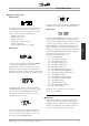
VLT® 2800 Series ■ Display readout Fr The frequency converter shows the present output frequency in Hertz [Hz]. Io The frequency converter shows the present output current in Amps [A]. Uo The frequency converter shows the present output voltage in Volt [V]. Ud The frequency converter shows the intermediate circuit voltage in Volt [V]. Po The frequency converter shows the calculated output in kilowatt [kW].
VLT® 2800 Series No.
VLT® 2800 Series when the motor frequency is reduced too quickly due to ramp down time being too short. When the inverter is switched off a trip reset is generated. Note: Voltage warning high (warning 5) will thus also be able to generate an alarm 7. WARNING/ALARM 8: Undervoltage If the intermediate circuit voltage (UDC) is lower than the inverter’s Undervoltage limit the inverter will be switched off until the UDC once more goes above the undervoltage limit.
VLT® 2800 Series WARNING/ALARM 34: HPFB communication fault Communication fault only occurs in Fieldbus versions. Regarding alarmtype, please see parameter 953 in fieldbus literature. Alarm 42, internal fault number 5: Fault in motor parameter database. ALARM 35: Inrush fault This alarm occurs when the frequency converter has been connected to the mains supply too many times within 1 minute. Alarm 44, internal fault number 7: Minimum software version of control card or BMC.
VLT® 2800 Series ■ Warning words, extended status words and Alarmwords Warning words, status words and Alarm words appear in the display in Hex format. If there are several warnings, status words or alarms, a total of all the warnings, status words or alarms will be displayed. Warning words, status words and alarm words can also be read out using the serial bus in parameters 540, 541 and 538 respectively.
VLT® 2800 Series ■ Special conditions ■ Aggressive environments As all other electronic equipment, a frequency converter contains a number of mechanical and electronic components, which to a varying extent are vulnerable to environmental impact. Consequently, the frequency converter is not to be installed in environments, where liquids, particles or gases are in the air that would impact and damage the electronics.
VLT® 2800 Series ■ Temperature-dependent switch frequency This function ensures the highest possible switch frequency without the frequency converter becoming thermally overloaded. The internal temperature is the actual expression of the degree to which the switch frequency can be based on the load, the ambient temperature, the supply voltage and the cable length.
VLT® 2800 Series VLT 2803-2875 Setup Emission Industrial environment Residential, commercial and light industry EN 55011 class 1A EN 55011 class 1B Cable-borne 150 kHz- 30 MHz Radiated 30 MHz - 1 GHz Cable-borne 150 kHz - 30 MHz Radiated 30 MHz - 1 GHz 3 x 480 V version with 1A RFI filter Yes 25 m screened/armoured Yes 25 m screened/armoured No No 3 x 480 V version with 1A RFI filter (R5: For IT mains) Yes 5 m screened/armoured Yes 5 m screened/armoured No No 1 x 200 V version with 1A R
VLT® 2800 Series • EN 55011: Emission Limits and methods of measurement of radio disturbance characteristics of industrial, scientific and medical (ISM) high-frequency equipment. Class 1A: Equipment used in an industrial environment. Class 1B: Equipment used in areas with a public supply network (residential, commerce and light industry). ■ UL Standard This device is UL-approved. 78 MG.28.A9.
VLT® 2800 Series ■ General technical data Mains supply (L1, L2, L3): Supply voltage VLT 2803-2815 220-240 V (N, L1) ...................................................... 1 x 220/230/240 V ±10% Supply voltage VLT 2803-2840 200-240 V ..................................................... 3 x 200/208/220/230/240 V ±10% Supply voltage VLT 2805-2882 380-480 V ..................................................... 3 x 380/400/415/440/480 V ±10% Supply voltage VLT 2805-2840 (R5) ....................................
VLT® 2800 Series Control card, analog inputs: Number of analog voltage inputs .................................................................................................................. 1 pcs. Terminal number ................................................................................................................................................ 53 Voltage level ......................................................................................................................
VLT® 2800 Series Control card, analog output: Number of programmable analog outputs ............................................................................................................ 1 Terminal number ................................................................................................................................................ 42 Current range at analog output ..........................................................................................................
VLT® 2800 Series Max. cross section to control cables, flexible cable .................................................................... 1 mm2/18 AWG Max. cross section to control cables, cable with enclosed core ............................................... 0.5 mm2/20 AWG When complying with EN 55011 1A and EN 55011 1B the motor cable must in certain instances be reduced. See EMC emission. Control characteristics: Frequency range .........................................................................
VLT® 2800 Series ■ Technical data, mains supply 1 x 220 240 V/3 x 200-240V According to . international standards Output current (3 x 200-240V) Output power (230 V) Typical shaft output Typical shaft output Max. cable cross section, motor Input current (1 x 220-240 V) Input current (3 x 200-240 V) Max. cable cross section, power Max. pre-fuses Efficiency3) Power loss at 100% load Weight Enclosure4 Type 2803 2805 2807 2811 2815 2822 2840 IINV. [A] IMAX (60s) [A] SINV.
VLT® 2800 Series ■ Technical data, mains supply 3 x 380 - 480 V According to international standards 2805 2807 2811 2815 2822 Output current IINV. [A] 1.7 2.1 3.0 3.7 5.2 7.0 (3 x 380-480V) IMAX (60s) [A] 2.7 3.3 4.8 5.9 8.3 11.2 SINV. [KVA] 1.1 1.7 2.0 2.6 3.6 4.8 3.0 Output power (400 V) Type 2830 Typical shaft output PM,N [kW] 0.55 0.75 1.1 1.5 2.2 Typical shaft output PM,N [HP] 0.75 1.0 1.5 2.0 3.0 4.0 4/10 4/10 4/10 4/10 4/10 4/10 Max.
VLT® 2800 Series ■ Available literature ■ Supplied with the unit Below is a list of the literature available for VLT 2800. It must be noted that there may be deviations from one country to the next. Supplied with the unit: Operating instructions ...................................................................................................................... MG.28.AX.YY Various literature for VLT 2800: Design Guide .........................................................................................
VLT® 2800 Series ■ Parameter list with factory settings PNU # 001 002 003 004 005 006 007 008 009 010 011 012 013 Parameter description Language Local/remote operation Local reference Active Setup Programming Setup Setup copying LCP copy Display scaling Large display readout Small display line 1.1 Small display line 1.2 Small display line 1.
VLT® 2800 Series PNU # 100 101 102 103 104 105 106 107 108 109 117 119 120 121 122 123 Factory setting 4-setup Speed reg., open loop Constant torque depends on unit depends on unit 50 Hz depends on motor selected depends on par. 102 Optimisation off depends on motor selected depends on motor selected OFF 0.0 sec 0.0 sec Coast in start del. Coast 0.1 Hz Yes Yes Yes Yes Yes Yes Yes Yes Yes Yes Yes Yes Yes Yes Yes Yes Conv. index 0 0 1 -2 -1 -2 0 0 -3 -2 0 -1 -1 0 0 -1 10 sec. OFF No protection 0.0 Hz 0.
VLT® 2800 Series PNU # 200 201 202 203 204 205 206 207 208 209 210 211 212 213 214 215 216 217 218 219 221 223 224 225 226 227 228 229 230 231 88 Parameter description Output frequency range Output frequency, low limit f MIN Output frequency, high limit f MAX Reference range Minimum ref RefMIN Maximum ref RefMAX Ramp type Ramp-up time 1 Ramp-down time 1 Ramp-up time 2 Ramp-down time 2 Jog ramp time Quick stop ramp-down time Jog frequency Reference function Preset reference 1 Preset reference 2 Preset refe
VLT® 2800 Series PNU # 302 303 304 Parameter description Digital input, term. 18 Digital input, term. 19 Digital input, term. 27 305 307 308 309 310 314 315 316 317 318 319 323 327 341 342 343 344 349 Digital input, term. 29 Digital input, term. 33 Term. 53, analogue input voltage Term. 53, min scaling Term. 53, max scaling Term. 60, analogue input current Term. 60, min scaling Term. 60, max scaling Time out Function after timeout Term. 42, analogue output Relay output Pulse ref./FB Term.
VLT® 2800 Series PNU # 400 405 406 409 411 412 413 414 415 416 417 418 419 420 421 423 424 425 426 427 428 437 438 439 440 441 442 443 444 445 451 452 456 461 90 Parameter description Brake function Reset function Aut. restart time Trip delay overcurrent Switching frequency Var. carrier frequency Overmodulation function Min. feedback Max. feedback Process units Speed PID propor.ampl. Speed PID intergra. Speed PID differentiation time Speed PID diff.
VLT® 2800 Series Parameter Factory setting description Address 1 Baudrate 9600 Baud Coasting stop Logic or Quick stop Logic or DC brake Logic or Start Logic or Reversing Logic or Selection of Setup Logic or Selection of preset ref. Logic or Bus jog 1 10.0 Hz Bus jog 2 10.0 Hz Telegram profile FC protocol Bus time interval 1 sec.
VLT® 2800 Series PNU # 600 601 602 603 604 605 615 616 617 618 619 620 621 624 625 626 627 628 630 632 634 635 640 641 642 Parameter Factory setting description Operating hours Hours run kWh counter Number of cut ins Number of overtemperatures Number of overvoltages Fault log: Error code Fault log: Time Fault log: Value Reset of kWh counter No reset Reset of running hours counter No reset Operation mode Normal operation Nameplate: Unit type Nameplate: Software version Nameplate: LCP identification no.
VLT® 2800 Series ■ Index Electrical installation ...................................................... 60 Electrical installation, control cables .................................. 66 EMC emission .............................................................. 76 A EMC-correct electrical installation ..................................... 59 AC brake .................................................................... 45 ETR - Electronic Thermal Relay ........................................
VLT® 2800 Series Mains connection ......................................................... 62 Reference function ........................................................ 31 Mains supply ............................................................... 83 Reference, .................................................................. 29 Manual initialisation ........................................................ 8 Relative .......................................................................
VLT® 2800 Series Torque characteristic .................................................... 18 U U/f-ratio ...................................................................... 25 Operation of the frequency converter UL Standard ................................................................ 78 V Variable torque ............................................................. 18 W Warning functions ........................................................