MAKING MODERN LIVING POSSIBLE VLT® 2800 The Quick Guide Phone: 800.894.0412 - Fax: 888.723.4773 - Web: www.ctiautomation.net - Email: info@ctiautomation.
VLT 2800 Quick Guide 1 Quick Guide 1 Quick Guide 1 1.1 Safety 1.1.1 Warnings High Voltage Warning: The voltage of the frequency converter is dangerous whenever it is connected to mains. Incorrect installation of the motor or frequency converter may cause damage to the equipment, serious injury or death. Consequently, it is essential to comply with the instructions in this manual as well as local and national rules and safety regulations.
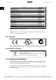
1 Quick Guide 1 VLT 2800 Quick Guide 1.1.2 Safety Instructions • The frequency converter must be disconnected from the mains if repair work is to be carried out. Check that the mains supply has been disconnected and the prescribed time has passed before removing motor and mains plugs. • Make sure the frequency converter is properly connected to earth. • Protect users against supply voltage. • Protect the motor against overloading according to national and local regulations.
VLT 2800 Quick Guide 1 Quick Guide 1.2 Introduction 1 Use this Quick Guide to carry out quick and EMC-correct installation of the frequency converter in five steps. Read the safety section before installing the unit. NB! The Operating Instructions, MG. 27.AX.YY, give further examples of installation and describe all functions in detail. The Design Guide, MG. 27.EX.YY, contains extensive information. 1.2.
1 Quick Guide VLT 2800 Quick Guide Title 1 VLT 2800 Operating Instructions VLT 2800 Design Guide VLT 2800 Data Sheet Mounting Instruction for VLT 2800 VLT 2800 Filter Instruction Precise Stop Cold Plate VLT 2800 NEMA 1 Terminal Covering VLT 2800 DeviceNet Cable VLT 2800 Blue Star Condensing Unit VLT 2880 - 2882 Spare Part Instruction Wobble Function VLT 2800 LCP Remote-mounting Kit User Instruction for LOP Brake Resistor Profibus DP Manual VLT 2800 DeviceNet Manual Metasys N2 Manual Profibus Manual Outp
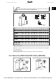
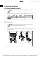
VLT 2800 Quick Guide 1 Quick Guide NB! With the IP 21 solution all units require a minimum of 100 mm air on each side. This means that side-by-side mounting is NOT allowed. Size mm S2 VLT 2803 - 2815 D2 VLT 2803 - 2815 VLT 2822* VLT 2840* PD2 VLT 2822 VLT 2840 T2 VLT 2822 VLT 2840 T4 VLT 2805 - 2815 VLT 2822 - 2840 VLT 2855 - 2875 VLT 2880 - 2882 A a B b C D E øa øb F øc 200 191 75 60 168 7 5 4.5 8 4 4.5 200 267.5 267.
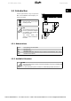
1 Quick Guide 1 VLT 2800 Quick Guide 1.3.2 Terminal cover The drawing below gives the dimensions for NEMA 1 terminal covers for VLT 2803-2875. Dimension 'a' depends on the unit type. 1.3.
VLT 2800 Quick Guide 1 Quick Guide 1 1.3.4 EMC filter for long motor cables Filter 192HA719 192H4720 192H4893 A 20 B 204 C 20 Dimensions øa D 5.5 8 E 234 F 27.5 G 244 H 75 A 20 H 90 A 20 H 140 I 45 B 273 I 50 B 273 I 50 øb 6 C 20 øb 6 C 20 øb 6 J 190 øa 5.5 J 257 øa 5.5 J 257 L 16 E 303 L 16 E 303 L 16 M 24 F 25 M 24 F 25 M 24 N 12 G 313 N 12 G 313 N 12 K 60 D 8 K 70 D 8 K 120 MG.28.M1.02 - VLT® is a registered Danfoss trademark Phone: 800.894.0412 - Fax: 888.723.4773 - Web: www.
1 Quick Guide 1 VLT 2800 Quick Guide 1.4 Electrical Installation 1.4.1 Electrical Installation in General NB! All cabling must comply with national and local regulations on cable cross-sections and ambient temperature. Copper conductors required, (60-75° C) recommended. Details of terminal tightening torques. VLT 2803 - 2875 2880 - 2882, 2840 PD2 Terminals Power mains brake Earth Power mains brake Earth Torque (Nm) 0.5 - 0.6 2-3 1.2 - 1.5 2-3 Torque, Control Cables (Nm) 0.22 - 0.25 Table 1.
VLT 2800 Quick Guide 1 Quick Guide 1 VLT 2880 - VLT 2882 Fit screened/armoured cable from the motor to the motor terminals of the frequency converter, i.e. U, V, W. The screen ends in a screen connector. 1.4.3 Mains connection NB! Please note that at 1 x 220-240 Volt the neutral wire must be attached to terminal N (L2) and the phase wire must be connected to terminal L1 (L1). No. No. No. No. No. No.
1 Quick Guide 1 VLT 2800 Quick Guide 1.4.4 Motor connection Connect the motor to terminals 96, 97, 98. Connect earth to terminal 99. See Technical data for correct dimensioning of cable cross-section. All types of three-phase asynchronous standard motors can be connected to a frequency converter. Normally, small motors are star-connected (230/400 V, Δ/ Y). NB! In motors without phase insulation paper, an LC filter should be fitted on the output of the frequency converter.
VLT 2800 Quick Guide 1 Quick Guide 1.4.6 Motor Cables See General Specifications for correct dimensioning of motor cable cross-section and length. See EMC Emissions for relationship between length and EMC emission. Always comply with national and local regulations on cable cross-section. 1 NB! If an unscreened/unarmoured cable is used, some EMC requirements are not complied with, see EMC test results in the Design Guide.
1 Quick Guide VLT 2800 Quick Guide 1 No. 01-03 12 18-33 20, 55 42 461 50 53 60 671 68, 691 701 Function Relay outputs 01-03 can be used for indicating status and alarms/warnings. 24 V DC voltage supply. Digital inputs. Common frame for input and output terminals. Analog output for displaying frequency, reference, current or torque. Digital output for displaying status, warnings or alarms, as well as frequency output. +10 V DC supply voltage for potentiometer or thermistor.
VLT 2800 Quick Guide 1 Quick Guide Connect all earthing systems to ensure the lowest possible conductor impedance. The lowest possible conductor impedance is achieved by keeping the conductor as short as possible and by grounding with the greatest possible surface area. If multiple drives are installed in a cabinet, the cabinet backplate, which must be made of metal, should be used as a joint earth reference plate. The drives must be fitted to the backplate at the lowest possible impedance.
1 Quick Guide 1 VLT 2800 Quick Guide 1.4.11 Extra protection RCD relays/ELCBs, multiple protective earthing or earthing can be used as extra protection, provided that local safety regulations are complied with. Three phase VLT frequency converters require an RCD type B. If an RFI filter is mounted in the drive and either the switch of the RCD or a manually operated switch is used to connect the drive to the mains voltage, a time delay of minimum 40 ms is required (RCD type B).
VLT 2800 Quick Guide 1 Quick Guide 1 1.4.13 Fuses Branch circuit protection: In order to protect the installation against electrical and fire hazard, all branch circuits in an installation, switch gear, machines etc., must be short-circuited and overcurrent protected according to national/international regulations.
1 Quick Guide VLT 2800 Quick Guide Alternative fuses 380-500 V drives VLT BussBussBuss2800 mann mann mann E52273 E4273 E4273 1 RK1/ JDDZ KTS-R20 J/JDDZ Bussmann E4273 T/JDDZ 2805JKS-20 JJS-20 2820 2855KTS-R25 JKS-25 JJS-25 2875 2880KTS-R50 JKS-50 JJS-50 2882 Alternative Fuses 200-240 V drives 2803KTN-R20 JKS-20 JJN-20 2822 2840 KTN-R25 JKS-25 JJN-25 Bussmann E4273 Bussmann E4273 SIBA E18027 6 Little FerrazFuse ShawE81895 mut E16326 7/E2137 FerrazShawmut E16326 7/ E2137 CC/JDDZ CC/JDDZ CC/JDDZ R
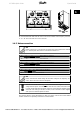
VLT 2800 Quick Guide 1 Quick Guide 1 1.5 Programming 1.5.1 Control Unit On the front of the frequency converter there is a control panel divided into four sections. 1. Six-digit LED display. 2. Keys for changing parameters and shifting display function. 3. Indicator lamps. 4. Keys for local operation.
1 Quick Guide VLT 2800 Quick Guide NB! If the [STOP/RESET] key is set at Not active [0] in parameter 014 Local stop/reset, and there is no stop command via the digital inputs or serial communication, the motor can only be stopped by disconnecting the mains voltage to the frequency converter. 1 [START] is used for starting the frequency converter. It is always active, but the [START] key cannot override a stop command. 1.5.3 Manual initialisation Disconnect mains voltage.
VLT 2800 Quick Guide 1 Quick Guide 1.5.7 Hand Auto During normal operation the frequency converter is in Auto mode, where the reference signal is given externally, analog or digital via the control terminals. However, in Hand mode, it is possible to give the reference signal locally via the control panel.
1 Quick Guide 1 VLT 2800 Quick Guide NB! VLT 2880-2882 do not have the AMT function. Set reference range Min. reference, RefMIN Parameter 204 Max. reference, RefMAX Parameter 205 Set ramp time Ramp-up time [s] Parameter 207 Ramp-down time [s] Parameter 208 In parameter 002, Local/remote control, the frequency converter mode can be selected as Remote operation [0], i.e. via the control terminals, or Local [1], i.e. via the control unit.
VLT 2800 Quick Guide 1 Quick Guide 1.7 Connection Examples 1 More examples can be found in the Operating Instructions (MG.27.AX.YY). 1.7.1 Start/Stop Start/stop using terminal 18 and coasting stop using terminal 27. Par. 302 Digital input = Start [7] Par. 304 Digital input = Coasting stop inverted [2] For Precise start/stop the following settings are made: Par. 302 Digital input = Precise start/ stop [27] Par. 304 Digital input = Coasting stop inverted [2] 1.
0-01 Language *[0] English [1] German [2] French [3] Danish [4] Spanish [5] Italian002 Local/Remote Operation *[0] Remote operation [1] Local operation 003 Local Reference If par. 013 = [1] or [2]: 0 - fMAX, *50 Hz If par. 013 = [3] or [4]: RefMIN - RefMAX, *0.
121 Start Function [0] DC hold during start delay time [1] DC brake during start delay time *[2] Coasting during start delay time [3] Start frequency/voltage clockwise [4] Start frequency/voltage in reference direction 122 Function at Stop *[0] Coasting [1] DC hold 123 Min. Frequency for Activation of Function at Stop 0.1 - 10 Hz, *0.1 Hz 126 DC Brake Time 0 - 60 s, *10 s 127 DC brake cut-in Frequency 0.0 (OFF) - Par.
[16] Speed up [17] Speed down [19] Catch up [20] Slow down [21] Ramp 2 [22] Preset ref, LSB [23] Preset ref, MSB [24] Preset reference on [25] Thermistor [26] Precise stop [27] Precise Start Stop [31] Selection of Set-up, LSB [32] Selection of Set-up, MSB [33] Reset and start [34 Pulse counter start 303 Terminal 19 Digital Input See par.
405 Reset Function *[0] Manual reset [1] Automatic reset x 1 [3] Automatic reset x 3 [10] Automatic reset x 10 [11] Reset at power-up 406 Automatic Restart Time 0 - 10 s, * 5 s 409 Trip Delay Overcurrent, ILIM 0 - 60 s (61 = OFF), * OFF 411 Switching Frequency 3000 - 14000 Hz (VLT 2803 - 2875), * 4500 Hz 3000 - 10000 Hz (VLT 2880 - 2882), * 4500 Hz 412 Variable Switching Frequency *[2] Without LC-filter [3] LC-filter connected 413 Overmodulation Function [0] OFF *[1] ON 414 Minimum Feedback, FBMIN -100,000.
1 Quick Guide 1 VLT 2800 Quick Guide 1.9.1 Warnings/alarm messages No.
VLT 2800 Quick Guide No. 50 51 54 55 56 99 1 Quick Guide Description AMT not possible W A T Cause of Problem X Either RS value is outside permitted limits, or motor current is too low on at least one phase, or the motor is too small for AMA. AMT fault re. nameplate daX Inconsistency between registered motor data. ta (AMT TYPE.DATA FAULT) AMT wrong motor (AMT X AMA has detected a missing motor phase.
1 Quick Guide 1 VLT 2800 Quick Guide 1.10 Specifications 1.10.1 Mains Suply 200 - 400 V According to . international Type 2803 2805 2807 2811 2815 2822 standards Output current IINV. [A] 2.2 3.2 4.2 6.0 6.8 9.6 IMAX (60s) [A] 3.5 5.1 6.7 9.6 10.8 15.3 (3 x 200-240V) Output power SINV. [KVA] 0.9 1.3 1.7 2.4 2.7 3.8 (230 V) Typical shaft outPM,N [kW] 0.37 0.55 0.75 1.1 1.5 2.2 put Typical shaft outPM,N [HP] 0.5 0.75 1.0 1.5 2.0 3.0 put Max.
VLT 2800 Quick Guide 1 Quick Guide According to international standards Output current (3 x 380-480V) Output power (400 V) Typical shaft output Typical shaft output Max. cable cross section, motor Input current (3 x 380-480 V) Max. cable cross section, power Max. pre-fuses Efficiency Power loss at 100% load Weight Enclosure Type 2840 2855 2875 2880 2881 2882 IINV. [A] IMAX (60s) [A] SINV. [KVA] 9.1 14.5 6.3 12 19.2 8.3 16 25.6 11.1 24 38.4 16.6 32.0 51.2 22.2 37.5 60.0 26.0 PM,N [kW] 4.
1 Quick Guide VLT 2800 Quick Guide Control card, digital inputs: Number of programmable digital inputs Terminal number Voltage level Voltage level, logic '0' Voltage level, logic '1' Maximum voltage on input Input resistance, Ri (terminals 18, 19, 27, 29) Input resistance, Ri (terminal 33) 1 5 18, 19, 27, 29, 33 0 - 24 V DC (PNP positive logic) < 5 V DC > 10 V DC 28 V DC approx. 4 kΩ approx.
VLT 2800 Quick Guide 1 Quick Guide Accuracy on frequency output Resolution on frequency output Max. error: 0.2 % of full scale 10 bit The digital output is galvanically isolated from the supply voltage (PELV) and other high-voltage terminals. See section entitled Galvanic Isolation in the Operating Instructions. Control card, analog output: Number of programmable analog outputs Terminal number Current range at analog output Max.
1 Quick Guide VLT 2800 Quick Guide Max. cross section to control wires, rigid wire 1.5 mm2/16 AWG (2 x 0.75 mm2) Max. cross section to control cables, flexible cable 1 mm2/18 AWG Max. cross section to control cables, cable with enclosed core 0.5 mm2/20 AWG 1 When complying with EN 55011 1A and EN 55011 1B the motor cable must in certain instances be reduced. See EMC emission. Control characteristics: Frequency range 0.2 - 132 Hz, 1 - 1000 Hz Resolution of output frequency 0.013 Hz, 0.
VLT 2800 Quick Guide 1 Quick Guide cabinet fitting with fresh-air circulation in the cabinet is recommended, thereby ensuring that aggressive gases are kept away from the frequency converter. 1 NB! Fitting of frequency converters in aggressive environments increases the risk of stoppages, in addition to considerably reducing the service life of the unit. Before the frequency converter is installed, it must be checked whether there are liquids, particles or gases in the air.