
Technical data


Bit 03, Coasting stop:
See description under Control word according to FC
protocol.
Bit 04, Quick stop:
See description under Control word according to FC
protocol.
Bit 05, Freeze output frequency:
See description under Control word according to FC
protocol.
Bit 06, Ramp stop/start:
See description under Control word according to FC
protocol.
Bit 07, Reset:
See description under Control word according to FC
protocol.
Bit 08, Jog 1:
Bit 08 = "1" means that the output frequency is deter-
mined by parameter 09 Bus jog 1.
Bit 09, Jog 2:
Bit 09 = "1" means that the output frequency is deter-
mined by parameter 510 Bus jog 2.
Bit 10, Data not valid/Data valid:
See description under Control word according to FC
protocol.
Bit 11, Slow-down:
Used to reduce the speed reference by the value in
parameter 219 Catch-up/slow-down reference.
Bit 11 = '0' does not cause any change to the refer-
ence.
Bit 11 = '1' means that the reference is reduced.
Bit 12, Catch-up:
Used to increase the speed reference by the value in
parameter 219 Catch-up/slow-down reference.
Bit 12 = '0' does not cause any change to the refer-
ence.
Bit 12 = '1' means that the reference is increased.
If both Slow down and Catch-up are activated (Bits 11
and 12 = "1"), slow down has the highest priority, i.e.
that the speed reference is reduced.
Bit 13/14, Selection of Setup:
See description under Control word according to FC
protocol.
Bit 15 Reversing:
See description under Control word according to FC
protocol.
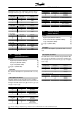
Status word according to Profidrive protocol
The status word is used to inform the master (e.g. a
PC) of the slave's (frequency converter) mode. Slave-
Master.
Bit Bit = 0 Bit =1
00 Control ready
01 Drive ready
02 Coasting stop
03 No trip Trip
04 ON 2 OFF 2
05 ON 3 OFF 3
06 Start enable Start disable
07 Warning
08 Speed ref. Speed = ref.
09 Local control Ser. communi.
10 Outside
frequency range
Frequency limit
OK
11 Motor running
12
13 Voltage warn.
14 Current limit
15 Thermal warn.
Bit 00, Control not ready/ready:
Bit 00 = '0' means that the Bit 00, 01 or 02 in the control
word are '0' (OFF1, OFF2 or OFF3) or the frequency
converter is not ready for operation.
Bit 00 = '1' means that the frequency converter is ready
for operation.
Bit 01, Drive ready:
See description under Status word according to FC
protocol.
Bit 02, Coasting stop:
Bit 02 = '0' means that Bits 00, 02 or 03 in the control
word are "0" (OFF1, OFF3 or Coasting stop).
Bit 02 = '1' means that Bits 00, 01, 02 and 03 in the
control word are "1", and that the frequency converter
has not tripped.
Bit 03, No trip/trip:
See description under Status word according to FC
protocol.
Bit 04, ON 2/OFF 2:
Bit 04 = '0' means that Bit 01 in the control word = '1'.
Bit 04 = '1' means that Bit 01 in the control word = '0'.
Bit 05, ON 3/OFF 3:
Bit 05 = '0' means that Bit 02 in the control word = '1'.
Bit 05 = '1' means that Bit 02 in the control word = '0'.
VLT
®
2800 Series
MG.27.E3.02 - VLT
®
is a registered Danfoss trademark 123
Programming