
Technical data
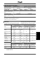

No. Description Warning Alarm Trip
locked
2 Live zero error (LIVE ZERO ERROR) X X X
4 Mains phase loss (MAINS PHASE LOSS) X X X
5 Voltage warning high (DC LINK VOLTAGE HIGH) X
6 Voltage warning low (DC LINK VOLTAGE LOW) X
7 Overvoltage (DC LINK OVERVOLT) X X X
8 Undervoltage (DC LINK UNDERVOLT) X X X
9 Inverter overload (INVERTER TIME) X X
10 Motor overloaded ( MOTOR, TIME) X X
11 Motor thermistor (MOTOR THERMISTOR) X X
12 Current limit (CURRENT LIMIT) X X
13 Overcurrent (OVERCURRENT) X X X
14 Earth fault (EARTH FAULT) X X
15 Switch mode fault (SWITCH MODE FAULT) X X
16 Short-circuit (CURR. SHORT CIRCUIT) X X
17 Serial communication timeout (STD BUS TIMEOUT) X X
18 HPFB bus timeout (HPFB TIMEOUT) X X
33 Out of frequency range (OUT FREQ RNG/ROT LIM) X
34 HPFB communication fault (PROFIBUS OPT. FAULT) X X
35 Inrush fault (INRUSH FAULT) X X
36 Overtemperature (OVERTEMPERATURE) X X
37-45 Internal fault (INTERNAL FAULT) X X
50 AMT not possible X
51 AMT fault re. nameplate data (AMT TYPE.DATA FAULT) X
54 AMT wrong motor (AMT WRONG MOTOR) X
55 AMT timeout (AMT TIMEOUT) X
56 AMT warning during AMT (AMT WARN. DURING AMT) X
99 Locked (LOCKED) X
LED indication
Warning
yellow
Alarm red
Trip locked yellow and red
WARNING/ALARM 2: Live zero fault
The voltage or current signal on terminal 53 or 60 is
below 50% of the preset value in parameter 309 or 315
Terminal, min. scaling.
WARNING/ALARM 4: Mains phase fault
No phase on mains supply side. Check the supply
voltage to the frequency converter. This fault is only
active in 3-phase mains supply. The alarm can also
occur when the load is pulsing. In this instance the
pulses must be dampened, e.g. using an inertia disc.
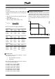
WARNING 5: Voltage warning high
If the intermediate circuit voltage (UDC) is higher than
Voltage warning high the frequency converter will give
a warning and the motor will continue to run un-
changed. If the UDC remains above the voltage warn-
ing limit, the inverter will trip after a set time. The time
depends on the device, and is set at 5 - 10 sec. Note:
The frequency converter will trip with an alarm 7 (over-
voltage). A voltage warning can occur when the con-
nected mains voltage is too high. Check whether the
supply voltage is suitable for the frequency converter,
see Technical data. A voltage warning can also occur
if the motor frequency is reduced too quickly due to
ramp down time being too short.
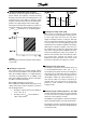
WARNING 6: Voltage warning low
If the intermediate circuit voltage (UDC) is lower than
Voltage warning low the frequency converter will give
a warning and the motor will continue to run un-
changed. A voltage warning can occur when the con-
nected mains voltage is too low. Check whether the
supply voltage is suitable for the frequency converter,
see Technical data. When the frequency converter is
switched off a brief warning 6 (and warning 8) appears.
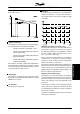
WARNING/ALARM 7: Overvoltage
If the intermediate voltage (UDC) goes over the inver-
ter's Overvoltage limit the inverter will be switched off
until the UDC has once more fallen below the over-
voltage limit. If the UDC remains above the overvoltag
limit the inverter will trip after a set time. The time de-
pends on the device, and is set at 5 - 10 sec. An
VLT
®
2800 Series
150 MG.27.E3.02 - VLT
®
is a registered Danfoss trademark