
Technical data

122 Function at stop
(FUNCTION AT STOP)
Value:
Coasting (COAST) [0]
DC hold (DC HOLD) [1]
Function:
This is where to choose the function of the frequency
converter after the output frequency has become lower
than the value in parameter 123 The min. frequency for
activation of function at stop or after a stop command
and when the output frequency has been ramped
down to 0 Hz.
Description of choice:
Select Coasting [0] if the frequency converter is to 'let
go' of the motor (inverter turned off).
Select DC hold [1] if parameter 137 DC hold voltage is
to be activated.
123
Min. frequency for activation of func-
tion at stop
(MIN.F.FUNC.STOP)
Value:
0,1 - 10 Hz
0,1 Hz
Function:
In this parameter, the output frequency is set at which
the function selected in parameter 122 Function at
stop is to be activated.
Description of choice:
Set the required output frequency.
NB!
If parameter 123 is set higher than param-
eter 130, then the start delay function (pa-
rameter 120 and 121) will be skipped.
NB!
If parameter 123 is set too high, and DC
hold has been chosen in parameter 122,
the output frequency will jump to the value
in parameter 123 without ramping up. This
may cause an overcurrent warning /
alarm.
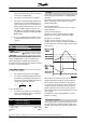
DC Braking
During DC braking DC voltage is supplied to the motor,
and this will cause the shaft to be brought to a stand-
still. In parameter 132 DC brake voltage DC brake
voltage can be preset from 0-100%. Max. DC brake
voltage depends on the motor data selected.
In parameter 126 DC braking time DC braking time is
determined and in parameter 127 DC brake cut-in fre-
quency the frequency at which DC braking becomes
active is selected. If a digital input is programmed to
DC braking inverse [5] and shifts from logic '1' to logic
'0', DC braking will be activated. When a stop com-
mand becomes active, DC braking is activated when
the output frequency is less than the brake cut-in fre-
quency.
NB!
DC braking may not be used if the inertia
in the motor shaft is more than 20 times
greater than the motor's internal inertia.
126 DC brake time
(DC BRAKING TIME)
Value:
0 - 60 sec.
10 sec
Function:
In this parameter, the DC brake time is set at which
parameter 132 DC brake voltage is to be active.
Description of choice:
Set the required time.
127 DC brake cut-in frequency
(DC BRAKE CUT-IN)
Value:
0.0 (OFF) - par. 202
Output frequency high limit, f
MAX
OFF
Function:
In this parameter, the DC brake cut-in frequency is set
at which the DC brake is to be activated in connection
with a stop command.
Description of choice:
Set the required frequency.
VLT
®
2800 Series
= factory setting, () = display text, [] = value for use in communication via serial communication port
74 MG.27.E3.02 - VLT
®
is a registered Danfoss trademark