VLT® 6000 HVAC Intr oduction to HV AC Introduction HVAC Introduction to HVAC ■ Contents Installation Software version .................................................................................................................. 3 Safety regulations ................................................................................................................ 4 Warning against unintended start ........................................................................................
VLT® 6000 HVAC Programming Control unit LCP ................................................................................................................ 69 Quick menu ....................................................................................................................... 74 The Setup configuration .................................................................................................... 75 Setup of user-defined readout ...........................................................
Introduction to HVAC VLT® 6000 HVAC VLT 6000 HVAC Design Guide Software version: 1.0x This Design Guide can be used with all VLT 6000 HVAC frequency converters that have software version 1.0x. See software version number in parameter 624 Software version no. MG.60.B1.
VLT® 6000 HVAC The voltage of the frequency converter is dangerous whenever the equipment is connected to mains. Incorrect installation of the motor or the frequency converter may cause damage to the equipment, serious personal injury or death. Consequently, the instructions in this manual, as well as national and local rules and safety regulations, must be complied with. ■ Safety regulations 1. The VLT frequency converter must be disconnected from mains if repair work is to be carried out.
VLT® 6000 HVAC This Design Guide is a tool intended to facilitate the sizing of systems in which VLT 6000 HVAC frequency converters are used. HVAC stands for Heating Ventilation Air-Conditioning. This Design Guide progresses step-by-step through the different procedures required for selecting, installing and programming a VLT 6000 HVAC. The Design Guide forms part of the literature concept supplied with VLT 6000 HVAC. However, the Design Guide is the most comprehensive document available.
VLT® 6000 HVAC ■ Introduction to the Design Guide Installation: This section shows you how to carry out correct mechanical installation of a VLT 6000 HVAC. In addition, the section has a description of how you ensure that the installation of the VLT 6000 HVAC is EMC-correct. Furthermore, the section includes a list of mains and motor connections, as well as a description of control card terminals. Programming: This section describes the control unit and the software parameters for the VLT 6000 HVAC.
VLT® 6000 HVAC Comes with VLT 6000 HVAC Operating Instructions MG.60.AX.YY Quick Setup MG.60.CX.YY X= YY = 01 = 02 = 03 = 04 = 05 = 06 = 07 = 10 = 20 = 28 = 51,52 = Other literature for VLT 6000 HVAC Design Guide MG.60.BX.YY VLT 6000 HVAC Data sheet MD.60.AX.YY version number language version Danish English German French Spanish Italian Swedish Dutch Finnish Brazilian-Portuguese Danish, English, German MG.60.B1.
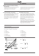
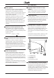
VLT® 6000 HVAC ■ Why use a frequency converter for controlling fans and pumps? A frequency converter takes advantage of the fact that centrifugal fans and pumps follow the laws of proportionality for such fans and pumps. ■ The clear advantage - energy savings The very clear advantage of using a frequency converter for controlling the speed of fans or pumps lies in the electricity savings to be obtained.
■ Example with varying flow over 1 year The example below is calculated on the basis of pump characteristics obtained from a pump data-sheet. (45 kW). The same examples of calculations can be used in the case of fan characteristics. The result obtained is savings in excees of 50% at the given flow distribution over a year, corresponding to 8,760 hours. Typically, the example calculated below results in a pay-back period of one year - depending on the price per kWh and the price of the frequency converter.
VLT® 6000 HVAC ■ Better regulation If a frequency converter is used for regulating the flow or pressure of a system, improved regulation is obtained which can be adjusted very precisely. A frequency converter can vary the speed of the fan or pump infinitely, thereby obtaining infinitely variable control of flow and pressure. Furthermore, a frequency converter can quickly regulate the speed of the fan or pump, so as to adapt it to new flow or pressure conditions in the system.
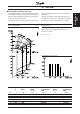
VLT® 6000 HVAC D.D.C. E.M.S. V.A.V. Sensor P Sensor T = Direct Digital Control = Energy Management System = Variable Air Volume = Pressure = Temperature Introduction to HVAC equency converter frequency ■ W ithout a fr The figure shows a fan system made in the traditional way. equency converter ■ W ith a fr frequency The figure shows a fan system controlled by VLT 6000 HVAC frequency converters. MG.60.B1.
VLT® 6000 HVAC ■ Control principle A frequency converter rectifies AC mains voltage into DC voltage, after which the DC voltage is converter into an AC current with a variable amplitude and frequency. 1. Mains voltage 3 x 200 - 240 V AC, 50 / 60 Hz 3 x 380 - 460 V AC, 50 / 60 Hz. 2. Rectifier A three-phase rectifier bridge that rectifies AC into DC current. 3. Intermediate circuit DC voltage = √2 x mains voltage [V]. 4.
VLT® 6000 HVAC After automatic motor adaptation, VVCPLUS will help to ensure extremely accurate motor control. Because of the good load estimation achieved, an energy optimisation algorithm can be integrated - one that is effective regardless of the load characteristic. - - The "flying start" function enables the unit to catch a rotating fan. Automatic ramp up/down to ensure that the VLT 6000 HVAC will not trip during acceleration or deceleration.
VLT® 6000 HVAC Advanced VLT protection Current measurement on all three motor phases provides perfect protection of VLT 6000 HVAC against earthing and short-circuiting faults on the motor connection. Constant monitoring of the three motor phases enables switching on the motor output, e.g. by means of a contactor. Efficient monitoring of the three mains supply phases ensures that the unit trips in the case of phase failure.
■ PC software and serial communication Danfoss offers various options for serial communication. Using serial communication makes it possible to monitor, programme and control one or several VLT 6000 HVAC from a centrally placed computer. For example, Danfoss offers an option card for Profibus. In addition, all VLT 6000 HVAC have an RS 485 port as standard, which enables them to communicate e.g. with a PC. A programme entitled VLT Software Dialog is available for this purpose.
VLT® 6000 HVAC ■ CE-labelling What is CE-labelling ? The purpose of CE-labelling is to avoid technical obstacles to trade within EFTA and the EU. The EU has introduced the CE-label as a simple way of showing whether a product complies with the relevant EU directives. The CE-label says nothing about the quality or specifications of a product.
■ Application examples The next few pages give typical examples of applications within HVAC. If you would like to receive further information about a given application, please ask your Danfoss supplier for an information sheet that gives a full description of the application. Variable Air Volume ........................................................................................................ page 18 Ask for The Drive to...Improving Variable Air Volume Ventilation systems MN.60.A1.
VLT® 6000 HVAC ■ Variable Air Volume VAV or Variable Air Volume systems, are used to control both the ventilation and temperature to satisfy the requirements of a building. Central VAV systems are considered to be the most energy efficient method to air condition buildings. By designing central systems instead of distributed systems, a greater efficiency can be obtained.
■ Constant Air Volume CAV, or Constant Air Volume systems are central ventilation systems usually used to supply large common zones with the minimum amounts of fresh tempered air. They preceded VAV systems and therefore are found in older multi-zoned commercial buildings as well. These systems preheat amounts of fresh air utilizing Air Handling Units (AHUs) with a heating coil, and many are also used to air condition buildings and have a cooling coil.
VLT® 6000 HVAC ■ Cooling Tower Fan Cooling Tower Fans are used to cool condenser water in water cooled chiller systems. Water cooled chillers provide the most efficient means of creating chilled water. They are as much as 20% more efficient than air cooled chillers. Depending on climate, Cooling towers are often the most energy efficient method of cooling the condenser water from chillers. They cool the condenser water by evaporation.
■ Condenser pumps Condenser Water pumps are primarily used to circulate water through the condenser section of water cooled chillers and their associated cooling tower. The condenser water absorbs the heat from the chillers condenser section and releases it into the atmosphere in the cooling tower. These systems are used to provide the most efficient means of creating chilled water, they are as much as 20% more efficient than air cooled chillers.
VLT® 6000 HVAC ■ Primary pumps Primary pumps in a primary/secondary pumping system can be used to maintain a constant flow through devices that encounter operation or control difficulties when exposed to variable flow. The primary/ secondary pumping technique decouples the “primary” production loop from the “secondary” distribution loop. This allows devices such as chillers to obtain constant design flow and operate properly while allowing the rest of the system to vary in flow.
■ Secondary pumps Secondary pumps in a primary/secondary chilled water pumping system are used to distribute the chilled water to the loads from the primary production loop. The primary/secondary pumping system is used to hydronically decouple one piping loop from another. In this case. The primary pump is used to maintain a constant flow through the chillers while allowing the secondary pumps to vary in flow, increase control and save energy.
VLT® 6000 HVAC ■ Specification text The following is a proposal for a HVAC frequency converter specification text that can be supplied with tender material. ■ Part 1 General 1.01 Section Includes A. This section covers the requirements necessary to furnish and install frequency converters. 1.02 Related Work A.
1.06 Quality Assurance A. The frequency converters shall be manufactured in accordance with ISO 9001: 1994 Quality Systems. B. To ensure quality and minimize failures at the jobsite, every frequency converter shall be tested by the manufacturer. The frequency converter shall operate a dynamometer at full load and the load and speed shall be cycled during the test. C. All optional features shall be functionally tested at the factory for proper operation. 1.07 Submittals A.
VLT® 6000 HVAC C. The frequency converter shall include Automatic Motor Adaptation (AMA), to optimize motor performance, improve start capabilities and compensate for motor cable variances. AMA shall be carried out at motor standstill with no need for detaching the load from the motor. D. The frequency converter and options shall be tested to ANSI/UL Standard 508.
L. Autoderating of the maximum drive current shall be incorporated in the frequency converter, to allow continued operation at reduced speed, in case of an overtemperature, phase loss or mains imbalance, without damaging the frequency converter. M. Full galvanic isolation with suitable potential separation from the power sources to ensure compliance with the PELV requirements of EN 50178. 2.06 Control A.
VLT® 6000 HVAC V. The frequency converter will sense the loss of load and signal a no load/broken belt warning or fault. W. The frequency converter shall store in memory the last 10 faults and record all operational data. X. Eight programmable digital inputs shall be provided for interfacing with the system‘s control and safety interlock circuitry. Y. Two programmable relay outputs shall be provided for remote indication of frequency converter status. Z.
2.09 SERVICE CONDITIONS A. Continuous operation at ambient temperature, 10 to +40°C (14 to 104°F), without derating. B. 0 to 95% relative humidity, non-condensing. C. Elevation to 3,300 feet without derating. D. AC line voltage variation, -10 to +10% of nominal voltage, while rated motor torque is maintained. E. No side clearance shall be required for cooling of wall mount units and all power and control wiring shall be done from the bottom. F.
VLT® 6000 HVAC ■ Ordering guide This section makes it easier for you to specify and order a VLT 6000 HVAC. ■ Choice of frequency converter The frequency converter should be chosen on the basis of the given motor current at maximum load on the system. The rated output current IVLT,N must be equal to or higher than the required motor current. VLT 6000 HVAC is available for two mains voltage ranges: 200-240 V and 380-460 V.
Mains voltage 380 - 415 V Typical shaft output PVLT.N VLT type 6002 6003 6004 6005 6006 6008 6011 6016 6022 6027 6032 6042 6052 6062 6075 6100 6125 6150 6175 6225 6275 [kW] 1.1 1.5 2.2 3.0 4.0 5.5 7.5 11 15 18.5 22 30 37 45 55 75 90 110 132 160 200 [kW] 1.1 1.5 2.2 3.0 4.0 5.5 7.5 11 15 18.5 22 30 37 45 55 75 90 110 132 160 200 Max continuous output power at 400 V SVLT.N [A] 3.0 4.1 5.6 7.2 10.0 13.0 16.0 24.0 32.0 37.5 44.0 61.0 73.0 90.0 106 147 177 212 260 315 368 [kVA] 2.2 2.9 4.0 5.2 7.2 9.3 11.
VLT® 6000 HVAC ■ Enclosure VLT 6000 HVAC is available with the following enclosures: - IP 00: IP 00: Bookstyle IP 20: Bookstyle IP 20: IP 20: IP 20: IP 54: IP 54: 30 to 45 kW / 200-240 V 55 to 200 kW / 380-460 V 1.1 to 3.0 kW / 200-240 V 1.1 to 7.5 kW / 380-460 V 1.1 to 45 kW / 200-240 V 1.1 to 200 kW / 380-460 V 1.1 to 45 kW / 200-240 V 1.1 to 200 kW / 380-460 V IP 00: This enclosure is only available for the larger power sizes of the VLT 6000 HVAC series.
■ Fieldbus protocols Danfoss VLT frequency converters are able to fulfil many different functions in an automated building management system. The VLT frequency converter can be integrated directly in an overall monitoring system. This means that detailed process data can be transmitted via serial communication. The protocols listed below are based on a RS 485 bus system with a maximum transmission speed of 9600 bauds.
VLT® 6000 HVAC ■ Unpacking and ordering a VLT frequency converter Are you are in doubt as to which VLT frequency converter you have received and which options it contains? Use the following table to find out. The table can also be used for ordering a VLT 6000 HVAC. ■ Type code ordering number string On the basis of your order, the VLT frequency converter is given an ordering number that can be seen from the nameplate on the unit.
VLT® 6000 HVAC H T VLT 6 ▲ ▲ ▲ ▲ D ▲ ▲ ▲ ▲ Power sizes e.g. 6008 Application range H HVAC Mains voltage ▲ 1.1 kW 1.5 kW 2.2 kW 3.0 kW 4.0 kW 5.5 kW 7.5 kW 11 kW 15 kW 18.
VLT® 6000 HVAC ■ Accessories for VLT 6000 HVAC IP 20 bottom cover Terminal cover Control unit IP 4x top cover Application option LCP ■ Ordering numbers, misc. Type Description Order no.
■ LC filters for VLT 6000 HVAC When a motor is controlled by a frequency converter, resonance noise will be heard from the motor. This noise, which is caused by the design of the motor, occurs each time one of the inverter switches in the frequency converter is activated. Consequently, the resonance noise frequency corresponds to the switching frequency of the frequency converter. For the VLT 6000 HVAC, Danfoss offers a LC filter to dampen the acoustic motor noise.
VLT® 6000 HVAC ■ Ordering numbers, LC filter modules Mains supply 3 x 200 - 240 V LC filter for VLT type 6002-6003 Bookstyle 6004-6005 Booksyle 6002-6005 6006-6008 6011 6016 6022 6027 6032 LC filter enclosure IP 20 Bookstyle IP 20 Bookstyle IP 20 IP 00 IP 00 IP 00 IP 00 IP 00 IP 00 Rated current at 200 V 7.8 A 15.2 A 15.2 A 25.0 A 32 A 46 A 61 A 73 A 88 A Max. output frequency 120 Hz 120 Hz 120 Hz 60 Hz 60 Hz 60 Hz 60 Hz 60 Hz 60 Hz Power loss Rated current at 400/460 V 7.2 A / 6.
VLT® 6000 HVAC The drawing on the left gives the measurements of IP 20 LC filters for the above-mentioned power range. Min. space above and under enclosure: 100 mm. IP 20 LC filters have been designed for side-by-side installation without any space between enclosures. Max. motor cable length: - 150 m screened/armoured cable - 300 m unscreened/unarmoured cable If EMC standards are to be complied with: - EN 55011-1B: Max. 50 screened/armoured cable Bookstyle: Max.
VLT® 6000 HVAC ■ LC filters VLT 6008-6032, 200 - 240 V / 6016-6062 380 - 460 V Max. motor cable length: The table and the drawing give the measurements of - 150 m screened/armoured cable IP 00 LC filters for Compact units. - 300 m unscreened/unarmoured cable IP 00 LC filters must be integrated and protected If EMC standards are to be complied with: against dust, water and corrosive gases. - EN 55011-1B: Max. 50 screened/armoured cable Bookstyle: Max. 20 m screened/armoured cable - EN 55011-1A: Max.
■ LC filter 6075-6275 380 - 460 V The table and the drawing give the measurements of IP 20 LC filters. IP 20 LC filters must be integrated and protected against dust, water and aggressive gases. Max. motor cable length: - 150 m screened/armoured cable - 300 m unscreened/unarmoured cable If EMC standards are to be complied with: - EN 55011-1B: Max. 50 m screened/armoured cable Bookstyle: Max. 20 m screened/armoured cable - EN 55011-1A: Max.
VLT® 6000 HVAC ■ General technical data Mains supply (L1, L2, L3): Supply voltage 200-240 V units ....................................................................... 3 x 200/208/220/230/240 V ±10% Supply voltage 380-460 V units ....................................................................... 3 x 380/400/415/440/460 V ±10% Supply frequency ...................................................................................................................................... 50/60 Hz Max.
VLT® 6000 HVAC Control card, pulse input: No. of programmable pulse inputs ....................................................................................................................... 3 Terminal nos. ......................................................................................................................................... 17, 29, 33 Max. frequency on terminal 17 ........................................................................................................................
VLT® 6000 HVAC ■ General technical data Cable lengths and cross-sections: Max. motor cable length, screened/armoured cable ..................................................................................... 150 m Max. motor cable length, unscreened/unarmoured cable ............................................................................. 300 m Max. motor cable length, screened/armoured cable VLT 6011 380-460 V .................................................... 100 m Max.
VLT® 6000 HVAC According to international requirements VL T type VLT Output current 4 ) Output (240 V) Typical shaft output Typical shaft output Max. cable cross-section to motor and DC-bus IVLT,N [A] IVLT, MAX (60 s) [A] SVLT,N [kVA] PVLT,N [kW] PVLT,N [HP] [mm2/AWG] Max. input current (200 V) IL,N [A] Max. cable cross-section power [mm2]/[AWG] 2 ) Max. pre-fuses [A]/UL 1 ) [A] Mains contactor [Danfoss type] [AC value] Efficiency 3) Weight IP 20 [kg] Weight IP 54 [kg] Power loss at max. load.
VLT® 6000 HVAC ■ Technical data, mains supply 3 x 380 - 460 V VL T type VLT 6002 6003 6004 6005 6006 6008 6011 Output current IVLT,N [A] (380-415 V) IVLT, MAX (60 s) [A] (380-415 V) IVLT,N [A] (440-460 V) IVLT, MAX (60 s) [A] (440-460 V) Output SVLT,N [kVA] (400 V) SVLT,N [kVA] (460 V) Typical shaft output PVLT,N [kW] Typical shaft output PVLT,N [HP] Max. cable cross-section to motor [mm2/AWG] 3.0 3.3 3.0 3.3 2.2 2.4 1.1 1.5 4.1 4.5 3.4 3.7 2.9 2.7 1.5 2 5.6 6.2 4.8 5.3 4.0 3.8 2.2 3 7.2 7.9 6.
VLT® 6000 HVAC According to international requirements VL T type VLT Output current IVLT,N [A] (380-415 V) IVLT, MAX (60 s) [A] (380-415 V) IVLT,N [A] (440-460 V) IVLT, MAX (60 s) [A] (440-460 V) Output SVLT,N [kVA] (400 V) SVLT,N [kVA] (460 V) Typical shaft output (380-415 V) PVLT,N [kW] Typical shaft output (440-460 V) PVLT, N [HP] Max. cross-section of copper cable to motor and DC-bus (380-415 V) [mm2] Max. cross-section of copper cable to motor and DC-bus (440-460 V) [mm2] Max.
VLT® 6000 HVAC ■ Mechanical dimensions All measurements in mm.
VLT® 6000 HVAC Installation ■ Mechanical dimensions MG.60.B1.
VLT® 6000 HVAC ■ Mechanical installation Please pay attention to the requirements that apply to integration and field mounting kit, see the below list. The information given in the list must be observed to avoid serious damage or injury, especially when installing large units. The VLT frequency converter must be installed vertically.
VLT® 6000 HVAC ■ Installation of VLT 6006-6032 200-240 V, VLT 6016-6062 380-460 V IP 20 and IP 54 Cooling Side-by-side IP 20 Installation All units in the above-mentioned series require a minimum of 200 mm of air above and below the enclosure and must be installed on a plane, vertical surface (no spacers). This applies both to IP 20 and IP 54 units. These units can be installed side by side without any spacing, since they do not require any cooling on the sides.
VLT® 6000 HVAC ■ General information about electrical installation ■ High voltage warning The voltage of the frequency converter is dangerous whenever the equipment is connected to mains. Incorrect installation of the motor or the frequency converter may cause damage to the equipment, serious personal injury or death. Consequently, the instructions in this Design Guide, as well as national and local safety regulations, must be complied with.
VLT® 6000 HVAC NB!: When the RFI switch is set to OFF parameter 407 Switching frequency max is allowed to be set to factory setting. NB! The VLT 6011/460 V has no RFI switch, since the factory setting is ON. NB! The RFI switch is not to be operated with mains supply connected to the unit. Check that the mains supply has been disconnected before operating the RFI switch. NB! The RFI switch disconnects the capacitors galvanically; however, transients higher than approx.
VLT® 6000 HVAC ■ EMC-correct electrical installation General points to be observed to ensure EMC-correct electrical installation: - Use only screened/armoured motor cables and screened/armoured control cables. Connect the screen to earth at both ends. Avoid installation with twisted screen ends (pigtails), since this ruins the screening effect at high frequencies. Use cable clamps instead.
VLT® 6000 HVAC ZT can be assessed on the basis of the following factors: - The contact resistance between the individual screen conductors. - The screen coverage, i.e. the physical area of the cable covered by the screen - often stated as a percentage value. Should be min. 85%. - The screen type, i.e. braided or twisted pattern. A braided pattern or a closed tube is recommended.
VLT® 6000 HVAC ■ Earthing of screened/armoured control cables Generally speaking, control cables must be screened/ armoured and the screen must be connected by means of a cable clamp at both ends to the metal cabinet of the unit. The drawing below indicates how correct earthing is carried out and what to be done if in doubt. Correct earthing Control cables and cables for serial communication must be fitted with cable clamps at both ends to ensure the best possible electrical contact.
VLT® 6000 HVAC Installation ■ VLT 6000 HVAC enclosures Bookstyle IP 20 VLT 6002-6005, 200-240 V VLT 6002-6011, 380-460 V Compact IP 20 VLT 6002-6005, 200-240 V VLT 6002-6011, 380-460 V Compact IP 54 VLT 6002-6005, 200-240 V VLT 6002-6011, 380-460 V IP 20 VLT 6006-6032, 200-240 V VLT 6016-6062, 380-460 V MG.60.B1.
VLT® 6000 HVAC ■ VLT 6000 HVAC enclosures IP 54 VLT 6006-6032, 200-240 V VLT 6016-6062, 380-460 V IP 20 VLT 6042-6062, 200-240 V VLT 6075-6125, 380-460 V 58 IP 00 VLT 6042-6062, 200-240 V VLT 6075-6125, 380-460 V IP 54 VLT 6042-6062, 200-240 V VLT 6075-6125, 380-460 V MG.60.B1.
Installation VLT® 6000 HVAC IP 00 VLT 6150-6275, 380-460 V IP 20 VLT 6150-6275, 380-460 V IP 54 VLT 6150-6275, 380-460 V MG.60.B1.
VLT® 6000 HVAC ■ Electrical installation, power cables 60 Bookstyle IP 20 VLT 6002-6005, 200-240 V VLT 6002-6011, 380-460 V Compact IP 20/IP 54 VLT 6002-6005, 200-240 V VLT 6002-6011, 380-460 V IP 20 VLT 6006-6032, 200-240 V VLT 6016-6062, 380-460 V IP 54 VLT 6006-6032, 200-240 V VLT 6016-6062, 380-460 V MG.60.B1.
VLT® 6000 HVAC Installation ■ Electrical installation, power cables IP 00/20 VLT 6042-6062, 200-240 V VLT 6075-6125, 380-460 V IP 54 VLT 6042-6062, 200-240 V VLT 6075-6125, 380-460 V IP 00/20 VLT 6150-6275, 380-460 V IP 54 VLT 6150-6275, 380-460 V MG.60.B1.
VLT® 6000 HVAC ■ Tightening-up torque and screw sizes The table shows the torque required when fitting terminals to the VLT frequency converter. For VLT 6002-6032, 200 -240 V, VLT 6002-6062, 380-460 V the cables must be fastened with screws. For VLT 6042-6062, 200-240 V and for VLT 6075-6275 the cables must be fastened with bolts. These figures apply to the following terminals: Nos. 91, 92, 93 Mains terminals L1, L2, L3 Motor terminals Nos. 96, 97, 98 U, V, W No.
VLT® 6000 HVAC ■ Direction of motor rotation Problems may arise at the start and at low rpm values if the motor sizes are widely different. This is because the relatively high ohmic resistance in small motors calls for a higher voltage at the start and at low rpm values. The factory setting is for clockwise rotation with the VLT frequency transformer output connected as follows.
VLT® 6000 HVAC ■ Motor thermal protection The electronic thermal relay in UL-approved VLT frequency converters has received UL-approval for single motor protection, as long as parameter 117 Motor thermal protection has been set to ETR Trip and parameter 105 Motor current, IVLT,N has been programmed for the rated motor current (can be read from the motor nameplate). ■ Control card All terminals for the control cables are located under the protective cover of the VLT frequency converter.
VLT® 6000 HVAC ■ Electrical installation, control cables Generally speaking, control cables must be screened/ armoured and the screen must be connected by means of a cable clamp at both ends to the metal cabinet of the unit (see instructions for installation page 57). Normally, the screen must also be connected to the body of the controlling unit (follow the instructions for installation given for the unit in question).
VLT® 6000 HVAC ■ Connection example, VLT 6000 HVAC The diagram below gives an example of a typical VLT 6000 HVAC installation. The mains supply is connected to terminals 91 (L1), 92 (L2) and 93 (L3), while the motor is connected to 96 (U), 97 (V) and 98 (W). These numbers can also be seen from the terminals of the VLT frequency converter. An external DC supply or a 12-pulse option can be connected to terminals 88 and 89. Please ask Danfoss for a Design Guide to learn more.
VLT® 6000 HVAC No. 04, 05 Function Relay output 1 can be used for indicating status and warnings. 12, 13 Voltage supply to digital inputs. For the 24 V DC to be used for digital inputs, switch 4 on the control card must be closed, position "on". 16-33 Digital inputs. See parameters 300-307 Digital inputs. 20 Common for digital inputs. 39 Common for analogue/digital outputs. Must be connnected to terminal 55 by means of a three-wire transmitter. See Examples of connection.
VLT® 6000 HVAC ■ Connection examples Single-pole start/stop - Start/stop using terminal 18. Parameter 302 = Start [1] - Quick-stop using terminal 27. Parameter 304 = Coasting stop, inverse [0] Digital speed up/down Run permissive - Start permitted with terminal 16. Parameter 300 = Start enabled [8]. - Start/stop with terminal 18. Parameter 302 = Start [1]. - Quickstop with terminal 27. Parameter 304 = Coasting stop, inverse [0]. - Activated damper (motor) Parameter 323 = Start command active [13].
■ Control unit LCP The front of the VLT frequency converter features a control panel - LCP (Local Control Panel). This is a complete interface for operation and programming of the VLT 6000 HVAC. The control panel is detachable and can - as an alternative - be installed up to 3 metres away from the VLT frequency converter, e.g. on the front panel, by means of a mounting kit option. The functions of the control panel can be divided into five groups: 1. Display 2. Keys for changing display mode 3.
VLT® 6000 HVAC [+/-] is used for selecting parameters and for changing a chosen parameter. These keys are also used to change the local reference. In addition, the keys are used in Display mode to switch between operation variable readouts. [<>] is used when selecting a parameter group and for moving the cursor when changing numerical values. ■ Indicator lamps At the bottom of the control panel is a red alarm lamp and a yellow warning lamp, as well as a green voltage LED.
VLT® 6000 HVAC Scroll-list: Resulting reference, % Resulting reference, unit Frequency % of maximum output frequency Motor current Power Power Output energy Hours run Used-defined readout Setpoint 1 Setpoint 2 Feedback 1 Feedback 2 Feedback Motor voltage DC-link voltage Thermal load on motor Thermal load on VLT Input status, dig.
VLT® 6000 HVAC ■ Display mode III: ■ Display mode IV: This display mode can be generated as long as the [DISPLAY MODE] key is kept depressed. In the first line, operating data names and units of operating data are displayed. In the second line, operating data 2 remains unchanged. When the key is released, the different operating data values are shown. REF% CURR.A POW.,KW 50.0Hz This display mode is only generated in connection with local reference, see also reference handling on page 60.
VLT® 6000 HVAC FREQUENCY 24.2 Hz SETUP 1 205 MAX. REFERENCE 000050,000 Hz ■ Infinitely variable change of numeric data value If the chosen parameter represents a numeric data value, a digit is first selected by means of the [<>] keys. FREQUENCY 50.0 HZ SETUP 1 209 JOG FREQUENCY 09.0 HZ Then the chosen digit is changed infinitely variably by means of the [+/-] keys: FREQUENCY 50.0 HZ SETUP 1 209 JOG FREQUENCY 10.0 HZ The chosen digit is indicated by the digit flashing.
VLT® 6000 HVAC ■ Quick menu The [QUICK MENU] key gives access to the 12 most important parameters of the VLT frequency converter. After programming, the VLT frequency [+] converter will in most cases be ready for operation. Scroll through the 12 of 12 Quick menu using the [+/-] RELAY 2 OUPUT keys and change the par. 326 [+] data values by 11 of 12 [-] pushing [CHANGE RELAY 1 OUTPUT DATA] + [OK]. 1 of 12 LANGUAGE par. 001 [+] 2 of 12 MOTOR POWER par. 102 [-] [-] [-] par.
VLT® 6000 HVAC Programming Using the [EXTEND MENU] key, it is possible to have access to all the parameters for the VLT frequency converter. ■ Operation and Display 000-017 This parameter group makes it possible to set up the control unit, e.g. with respect to language, display readout and the possibility of making the function keys on the control unit inactive.
VLT® 6000 HVAC Connection examples Setup change 004 LCP copy (LCP COPY) Value: ✭ No copying (NO COPY) Upload all parameters (UPLOAD ALL PARAMET.) Download all parameters (DOWNLOAD ALL PARAM.) Download power-independent par. (DOWNLOAD SIZE INDEP.) [1] [2] [3] Function: Parameter 004 LCP copy is used if the integrated copying function of the control panel is to be used. This function is used if all parameter Setups are to be copied from one VLT frequency converter to another by moving the control panel.
VLT® 6000 HVAC 005 Max. value of user-defined readout (CUSTOM READOUT ) Value: ✭100.00 0.01 - 999,999.99 Description of choice: Set the required value for max. output frequency. 006 Unit for user-defined readout (CUST. READ.
VLT® 6000 HVAC Setpoint 1 [unit] (SETPOINT 1 [UNITS]) Setpoint 2 [unit] (SETPOINT 2 [UNITS]) Feedback 1 (FEEDBACK 1 [UNITS]) Feedback 2 (FEEDBACK 2 [UNITS]) Feedback [unit] (FEEDBACK [UNITS]) Motor voltage [V] (MOTOR VOLTAGE [V]) DC link voltage [V] (DC VOLTAGE [V]) Thermal load, motor [%] (THERM.MOTOR LOAD [%]) Thermal load, VLT [%] (THERM.
VLT® 6000 HVAC Analogue input 54 [V] states the voltage value on terminal 54. Analogue input 60 [mA] states the voltage value on terminal 60. Pulse reference [Hz] states a pulse frequency in Hz connected to terminal 17 or terminal 29. External reference [%] gives the sum of the external references as a percentage (the sum of analogue/ pulse/serial communication) in the range from Minimum reference, RefMIN to Maximum reference, RefMAX. Heat sink temp.
VLT® 6000 HVAC 013 OFF/STOP on LCP (STOP BUTTON) Value: Disable (DISABLE) ★ Enable (ENABLE) [0] [1] Function: This parameter allows selection/deselection of the local stop key on the control panel. Description of choice: If Disable [0] is selected in this parameter, the [OFF/ STOP] key will be inactive. NB! If Disable is selected, the motor cannot be stopped by means of the [OFF/STOP] key.
VLT® 6000 HVAC ■ Load and Motor 100-117 This parameter group allows the configuration of regulation parameters and the choice of torque characteristics to which the VLT frequency converter is to be adapted. The motor nameplate data must be set and automatic motor adaptation can be carried out. In addition, DC brake parameters can be set and the motor thermal protection can be activated.
VLT® 6000 HVAC NB! It is important that the values set in parameters 102-106 Nameplate data correspond to the nameplate data of the motor with respect to either star coupling Y or delta coupling ∆. 102 Motor power, PM,N (MOTOR POWER) Value: 0.25 kW (0.25 KW) [25] 0.37 kW (0.37 KW) [37] 0.55 kW (0.55 KW) [55] 0.75 kW (0.75 KW) [75] 1.1 kW (1.10 KW) [110] 1.5 kW (1.50 KW) [150] 2.2 kW (2.20 KW) [220] 3 kW (3.00 KW) [300] 4 kW (4.00 KW) [400] 5,5 kW (5.50 KW) [550] 7,5 kW (7.50 KW) [750] 11 kW (11.
VLT® 6000 HVAC 104 Motor frequency, fM,N (MOTOR FREQUENCY) Value: ★ 50 Hz (50 Hz) 60 Hz (60 Hz) [50] [60] Function: This is where the rated motor frequency fM,N is selected. Description of choice: Select a value that equals the nameplate data on the motor. Furthermore, it is also possible to set the value for motor frequency infinitely variably in the 24-1000 Hz range. 105 Motor current, IM,N (MOTOR CURRENT) Value: 106 Rated motor speed, nM,N (MOTOR NOM. SPEED) Value: 100 - fM,N x 60 (max.
VLT® 6000 HVAC It is possible via parameter 107 Automatic motor adaptation, AMA to choose whether a complete automatic motor adaptation Automatic adaptation [1] is to be carried out, or whether reduced automatic motor adaptation Automatic adaptation with LC-filter [2] is to be made. It is only possible to carry out the reduced test if a LC-filter has been placed between the VLT frequency converter and the motor.
VLT® 6000 HVAC 109 Resonance damping (RESONANCE DAMP.) Value: ★100 % Function: High-frequency electric resonance problems between the VLT frequency converter and the motor can be eliminated by adjusting the resonance damping. Description of choice: Adjust the damping percentage until the motor resonance has disappeared. 110 High break-away torque (HIGH START TORQ.) Value: 0.0 - 0.5 sec. ★ 0.0 sec. Function: In order to secure a high starting torque, the maximum torque for max. 0.5 sec. is allowed.
VLT® 6000 HVAC ■ DC braking In DC braking, the motor receives a DC current that brings the shaft to a halt. Parameter 114 DC braking current, decides the DC braking current as a percentage of the rated motor current IM,N. In parameter 115 DC braking time, the DC braking time is selected, and in parameter 116 DC brake cutin frequency, the frequency is selected at which DC braking becomes active.
VLT® 6000 HVAC 117 Motor thermal protection (MOT.
VLT® 6000 HVAC ■ References & Limits 200 - 228 In this parameter group, the frequency and reference range of the VLT frequency converter are established. 202 Output frequency high limit, fMAX (MAX. FREQUENCY) Value: fMIN - 120/1000 Hz (par. 200 Output frequency range) ★ 50 Hz Function: In this parameter, a maximum output frequency limit can be selected that corresponds to the highest speed at which the motor can be.
VLT® 6000 HVAC ■ Reference handling Reference handling is shown in the block diagram underneath. The block diagram shows how a change in a parameter can affect the resulting reference. Parameters 203 to 205 Reference handling, minimum and maximum reference and parameter 210 Reference type define the way reference handling can be carried out. The mentioned parameters are active both in a closed and in an open loop.
VLT® 6000 HVAC 203 Reference site (REFERENCE SITE) Value: ★ Hand/Auto linked reference (LINKED TO HAND/AUTO)) Remote reference (REMOTE) Local reference (LOCAL) [0] [1] [2] Function: This parameter decides which resulting reference is to be active. If Hand/Auto linked reference [0] is selected, the resulting reference will depend on whether the VLT frequency converter is in Hand or Auto mode.
VLT® 6000 HVAC Function, cont.: The reference unit can be determined on the basis of the following table: Description of choice: Program the desired ramp-down time. Unit Hz Par. 100 Configuration = Closed loop Par. 415 Description of choice: Maximum reference is set if the motor speed is not to exceed the set value, regardless of whether the resulting reference is higher than Maximum reference. 206 Ramp-up time (RAMP UP TIME) Value: 1 - 3600 sec.
VLT® 6000 HVAC ■ Reference type The example shows how the resulting reference is calculated when Preset references are used together with Sum and Relative in parameter 210 Reference type. A formula for calculating the resulting reference is given on page 156. See also the drawing on page 89. The following parameters have been set: Par. 204 Minimum reference: 10 Hz Par. 205 Maximum reference: 50 Hz Par. 211 Preset reference: 15% Par. 308 Terminal 53, analogue input: Reference [1] Par. 309 Terminal 53, min.
VLT® 6000 HVAC -100.00 % - +100.00 % ★ 0.00% of the reference range/external reference Function: Four different preset references can be programmed in parameters 211-214 Preset reference. The preset reference is stated as a percentage value of the reference range (RefMIN - RefMAX) or as a percentage of the other external references, depending on the choice made in parameter 210 Reference type. The choice between the preset references can be made by activating terminal 16, 17, 29, 32 or 33, cf.
VLT® 6000 HVAC 221 Warning: Low current, ILOW (WARN. LOW CURR.) Value: 0.0 - par. 222 Warning: High current, IHIGH 222 Warning: High current, IHIGH (WARN. HIGH CURR.) Value: ✭0.0A Function: When the motor current is below the limit, ILOW, programmed in this parameter, the display shows a flashing CURRENT LOW, provided Warning [1] has been selected in parameter 409 Function in case of no load. The VLT frequency converter will trip if parameter 409 Function in case of no load has been selected as Trip [0].
VLT® 6000 HVAC Par. 200 Output frequency range = 0-1000 Hz [1]. parameter 223 - 1000 Hz ✭ 120.0 Hz Function: If the output frequency is above the limit, fHIGH, programmed in this parameter, the display will show a flashing FREQUENCY HIGH. The warning functions in parameters 221-228 are not active during ramp-up after a start command, rampdown after a stop command or while stop-ped. The warning functions are activated when the output frequency has reached the resulting reference.
VLT® 6000 HVAC Description of choice: The upper signal limit, RefHIGH,of the reference must be programmed within the normal working range of the frequency converter, provided parameter 100 Configuration has been programmed for Open loop [0]. In Closed loop [1] (parameter 100), RefHIGH must be within the reference range programmed in parameters 204 and 205. 227 Warning: Low feedback, FBLOW (WARN LOW FDBK) Value: -999,999.999 - FBHIGH (parameter 228) ★ -999.
VLT® 6000 HVAC ■ Inputs and outputs 300-328 In this parameter group, the functions that relate to the input and output terminals of the VLT frequency converter are defined. The digital inputs (terminals 16, 17, 18, 19, 27, 32 and 33) are programmed in parameters 300-307. The table below gives the options for programming the inputs. The digital inputs require a signal of 0 or 24 V DC. A signal lower than 5 V DC is a logic ‘0’, while a signal higher than 10 V DC is a logic ‘1’.
VLT® 6000 HVAC Function: In parameters 300-307 Digital inputs it is possible to choose between the different possible functions related to the digital inputs (terminals 16-33). The functional options are given in the table on the previous page. Description of choice: No function is selected if the VLT frequency converter is not to react to signals transmitted to the terminal.
VLT® 6000 HVAC Preset ref. 1 Preset ref. 2 Preset ref. 3 Preset ref. 4 Preset ref. msb 0 0 1 1 Preset ref. lsb 0 1 0 1 Speed up and Speed down are selected if digital control of the up/down speed is desired. This function is only active if Freeze reference or Freeze output has been selected. As long as there is a logic ‘1’ on the terminal selected for Speed up, the reference or the output frequency will increase by the Ramp-up time set in parameter 206.
VLT® 6000 HVAC ■ Analogue inputs Two analogue inputs for voltage signals (terminals 53 and 54) are provided for reference and feedback signals. Furthermore, an analogue input is available for a current signal (terminal 60). A thermistor can be connected to voltage input 53 or 54. The two analogue voltage inputs can be scaled in the range of 0-10 V DC; the current input in the range of 0-20 mA. Analogue inputs terminal no.
VLT® 6000 HVAC Scaling of the input signal is effected in parameter 312 Terminal 54, min. scaling and in parameter 313 Terminal 54, max. scaling. 309 Terminal 53, min. scaling (AI 53 SCALE LOW) Value: ★ 0.0 V Function: This parameter is used for setting the signal value that has to correspond to the minimum reference or the minimum feedback, parameter 204 Minimum reference, RefMIN/413 Minimum feedback, FBMIN. See Reference handling on page 89 or Feedback handling on page 115.
VLT® 6000 HVAC 314 Terminal 60, analogue input current (AI [mA] 60 FUNCT.) Value: See description of parameter 308. ★ Reference Function: This parameter allows a choice between the different functions available for the input, terminal 60. Scaling of the input signal is effected in parameter 315 Terminal 60, min. scaling and in parameter 316 Terminal 60, max. scaling. Description of choice: See description of parameter 308 Terminal 53, analogue input voltage. 315 Terminal 60, min.
VLT® 6000 HVAC Analogue/digital outputs terminal no. parameter 0-20 mA, 4-20 mA or 0-32000 pulses (depending on the value set in parameter 322 Terminal 45, output, pulse scaling. If the output is used as a voltage output (0-10 V), a pull-down resistor of 470 Ω (max. 500 Ω) should be fitted to terminal 39 (common for analogue/digital outputs). If the output is used as a current output, the resulting impedance of the connected equipment should not exceed 500 Ω. .
VLT® 6000 HVAC Function: This output can act both as a digital or an analogue output. If used as a digital output (data value [0]-[59]), a 0/24 V DC signal is transmitted; if used as an analogue output, either a 0-20 mA signal, a 4-20 mA signal or a pulse sequence of 0-32000 pulses is transmitted. Description of choice: No function. Selected if the VLT frequency converter is not to react to signals. Drive ready ready..
VLT® 6000 HVAC Out of feedback range. The feedback signal is outside the range programmed in parameter 227 Warning: Low feedback, FBLOW and 228 Warning: High feedback, FBHIGH. Out of reference range. The reference lies outside the range programmed in parameter 225 Warning: Low reference, RefLOW and 226 Warning, High reference, RefHIGH. 320 Terminal 42, output, pulse scaling (AO 42 PULS SCALE) Value: 1 - 32000 Hz ★ 5000 Hz Function: This parameter allows scaling of the pulse output signal.
VLT® 6000 HVAC ■ Relay outputs Relay outputs 1 and 2 can be used to give the present status or a warning. Relay 2 4 - 5 make Max. 50 V AC, 1 A, 60 VA. Max. 75 V DC, 1 A, 30 W. The relay is placed on the control card, see page 65. Relay 1 1 - 3 break, 1 - 2 make Max. 240 V AC, 2 Amp. The relay is placed with the mains and motor terminals. Relay outputs Relay no. parameter Value: No function (NO FUNCTION) Ready signal (READY) Standby (STAND BY) Running (RUNNING) Running at ref.
VLT® 6000 HVAC 323 Relay 1, output function (RELAY1 FUNCTION) Function: This output activates a relay switch. Relay switch 01 can be used for bringing status and warnings. The relay is activated when the conditions for the relevant data values have been fulfilled. Activation/deactivation can be programmed in parameter 324 Relay 1, ON delay and parameter 325 Relay 1, OFF delay. See technical data page 43. Function: This output activates a relay switch.
VLT® 6000 HVAC ■ Application functions 400-427 In this parameter group, the special functions of the VLT frequency converter are set up, e.g. PID regulation, setting of the feedback range and the Setup of the Sleep mode function. Additionally, this parameter group includes: - Reset function. - Flying start. - Option of interference reduction method. - Setup of any function upon loss of load, e.g. because of a damaged V-belt. - Setting of switching frequency. - Selection of process units.
VLT® 6000 HVAC ■ Sleep mode Sleep mode makes it possible to stop the motor when it is running at low speed and thus has almost no load. If consumption in the system goes back up, the VLT frequency converter will start the motor and supply the power required. NB! Energy can be saved with this function, since the motor is only in operation when the system needs it. Sleep mode is not active if Local reference or Jog has been selected The function is active in both Open loop and Closed loop.
VLT® 6000 HVAC 403 Sleep mode timer (SLEEP MODE TIMER) Value: 0 - 300 sec.(OFF) 406 Boost setpoint (BOOST SETPOINT) Value: 0 - 200 % Function: This parameter enables the VLT frequency converter to stop the motor if the load on the motor is minimal. The timer in parameter 403 Sleep mode timer starts when the output frequency drops below the frequency set in parameter 404 Sleep frequency. When the time set in the timer has expired, the VLT frequency converter will turn off the motor.
VLT® 6000 HVAC ★ ASFM (ASFM) Fixed switching frequency (FIXED SWITCHING FREQ.) LC filter fitted (LC-FILTER CONNECTED) 412 Trip delay overcurrent, ILIM (OVERLOAD DELAY) Value: [0] [1] [2] Function: Used to select different methods for reducing the amount of acoustic interference from the motor. Description of choice: ASFM [0] guarantees that the maximum switching frequency is used at all times without derating of the VLT frequency converter. This is done by monitoring the load.
VLT® 6000 HVAC ■ Feedback signals in open loop Normally, feedback signals and thus feedback parameters are only used in Closed loop operation; in VLT 6000 HVAC units, however, the feedback parameters are also active in Open loop operation. In Open loop mode, the feedback parameters can be used to show a process value in the display.
VLT® 6000 HVAC Correction for voltage losses in long signal cables can be carried out when using a transmitter with a voltage output. This is done in parameter group 300 Min./ Max. scaling. Feedback The feedback signal must be connected to a terminal on the VLT frequency converter. Use the list below to decide which terminal to use and which parameters to program.
VLT® 6000 HVAC ■ PID for process regulation, cont. Inverse regulation Normal regulation means that the motor speed increases when the reference/setpoint is higher than the feedback signal. If there is a need for inverse regulation, in which the speed is reduced when the feedback signal is lower than the reference/setpoint, Inverse must be programmed in parameter 420 PID normal/inverse control. Anti Windup The process regulator is factory preset with an active anti-windup function.
VLT® 6000 HVAC ■ PID overview The block diagram below shows reference and setpoint in relation to the feedback signal. In addition, the VLT 6000 HVAC has an integral calculator capable of converting a pressure signal into a "linear flow" feedback signal. This function is activated in parameter 416 Feedback conversion. The parameters for feedback handling are active both in closed and open loop modes.
VLT® 6000 HVAC Feedback handling, cont. 416 Feedback conversion (FFEEDBACK CONV.) Value: ★ Linear (LINEAR) Square root (SQUARE ROOT) [0] [1] Function: In this parameter, a function is selected which converts a connected feedback signal from the process to a feedback value that equals the square root of the connected signal. This is used, e.g. where regulation of a flow (volume) is required on the basis of pressure as feedback signal (flow = constant x √pressure).
VLT® 6000 HVAC [0] [1] [2] [3] [4] [5] [6] Function: This parameter allows a choice between different calculation methods whenever two feedback signals are used. Description of choice: If Minimum [0] is selected, the VLT frequency converter will compare feedback 1 with feedback 2 and regulate on the basis of the lower feedback value. Feedback 1 = Sum of parameter 535 Bus feedback 1 and the feedback signal value of terminal 53.
VLT® 6000 HVAC 419 Setpoint 2 (SETPOINT 2) Value: RefMIN - RefMAX ★ 0.000 Function: Setpoint 2 is used in closed loop as the reference to compare the feedback values with. See description of parameter 417 Feedbackfunction. The setpoint can be offset with digital, analog or bus signals, see reference handling. Used in Closed loop [1] parameter 100 Configura-tion and only if 2-zone minimum/maximum is selected in parameter 417 Feedbackfunction. Description of choice: Set the required value.
VLT® 6000 HVAC Description of choice: Set the required start frequency. NB! If the VLT frequency converter is running at the current limit before the desired start frequency is obtained, the process regulator will not be activated. For the regulator to be activated anyway, the start frequency must be lowered to the required output frequency. This can be done during operation. 425 PID differentiation time (PID DIFF. TIME) Value: 423 PID proportional gain (PID PROP. GAIN) Value: 0.00 (OFF) - 10.00 sec.
VLT® 6000 HVAC 427 PID lowpass filter time (PID FILTER TIME) Value: 0.01 - 10.00 ★ 0.01 Function: Oscillations on the feedback signal are dampened by the lowpass filter in order to reduce their impact on the process regulation. This can be an advantage e.g. if there is a lot of noise on the signal. Used in Closed loop [1] (parameter 100). Description of choice: Select the desired time constant (τ). If a time constant (τ) of 0.1 s is programmed, the break frequency for the lowpass filter will be 1/0.
VLT® 6000 HVAC ■ Serial communication for FC protocol Master Serial communication Slave 1 Slave 2 Slave 31 (126) Address 1 Address 2 Address 31 (126) If Danfoss FC protocol is to be selected, set parameter 500 Protocol to FC protocol [0]. A description of Johnson's Control Metasys N2 and Landis/Staefa FLN is not included in this Design Guide. For further information on Metasys N2, please order MI.60.XX.XX from your Danfoss supplier. For further information on FLN, please order MI.60.XX.
VLT® 6000 HVAC Each transferred character begins with a start bit. Subsequently, 8 data-bits are transferred, corresponding to one byte. Each character is secured via a parity bit set to "1" when there is even parity (i.e. an even number of binary 1's in the 8 data-bits and the parity bit combined). A character ends with a stop bite and thus consists of a total of 11 bits. The time between individual characters in a telegram is not to exceed 2 characters and the telegram must be completed within 1.
VLT® 6000 HVAC 1. Address format 1-126 The byte for the 1-126 address range has the following profile: 6 5 4 3 2 1 0 Bit 7 = 1 (address format 1-126 active) Bit 0-6 = VLT frequency converter address 1-126 Bit 0-6 = 0 Broadcast The slave sends the address byte back to the master in the reply telegram in unchanged form.
VLT® 6000 HVAC If the command cannot be carried out, the slave will send this reply (0111) Command cannot be executed and give the following error message in the parameter value (PWE): 1. Parameter bytes PKE IND PWEHIGH PWELOW (reply 0111) 0 AK PNU Parameter number Not in use Parameter commands and replies 15 14 13 12 11 10 9 8 7 6 5 4 3 2 1 0 Parameter commands and replies (AK) Bits no.
VLT® 6000 HVAC Example - Index: The first error code (index [1]) in parameter 615 Error code must be read. The index character is used to indicate whether the command in question is a read or write command. For a read command, the index must have the following format: PKE = 1267 Hex (read parameter 615 Error code). IND = 0001 Hex - Index no. 1.
VLT® 6000 HVAC Parameter 202 Output frequency high limit, fMAX is to be changed to 100 Hz. This value must be remember after a power failure, so it is written in EEPROM. The value in parameter 206 Ramp-up time is required. The master sends the following enquiry: PKE = PKE = E0CA Hex - Write to parameter 202 Output frequency high limit, fMAX IND = 0000 Hex PWEHIGH = 0000 Hex PWELOW = 03E8 Hex - Data value 1000, corresponding to 100 Hz, see Conversion.
VLT® 6000 HVAC Example: Parameter 201: minimum frequency, conversion factor 0.1. If parameter 201 is to be set to 10 Hz, a value of 100 must be transferred, since a conversion factor of 0.1 means that the transferred value will be multiplied by 0.1. A value of 100 will thus be understood as 10.0. ■ Process word The process word block is divided into two blocks each of 16 bits, which always come in the sequence stated.
VLT® 6000 HVAC Bit 03, Coasting stop: Bit 03 = "0" means that the VLT frequency converter immediately "lets go" of the motor (the output transistors are "turned off"), which means that the motor runs freely until it stops. Bit 03 = "1" means that the frequency converter is able to start the motor, provided the other conditions for starting are fulfilled. Note: In parameter 503 Coasting stop the choice is made of how bit 03 is to be gated with the corresponding function of terminal 27.
VLT® 6000 HVAC ■ Status word as per FC protocol The status word is used to inform the master (e.g. a PC) of the condition of the slave (VLT 6000 HVAC). Slave➝Master Status word Output frequency Bit 04, Not in use: Bit 04 is not used in the status word. Bit 05, Not in use: Bit 05 is not used in the status word. Bit 06, Not in use: Bit 06 is not used in the status word. 15 14 13 12 11 10 9 8 7 6 5 4 3 2 1 0 Bit no.
VLT® 6000 HVAC Bit 12, No function: Bit 12 has no function. Bit 13, Voltage warning high/low: Bit 13 = "0" means that there is no voltage warning. Bit 13 = "1" means that the DC voltage of the VLT 6000 HVAC intermediate circuit is too low or too high. See the voltage limits on page 151. Bit 14, Current limit: Bit 14 = "0" means that the output current is smaller than the value in parameter 215 Current limit ILIM.
VLT® 6000 HVAC ■ Present output frequency Status word Output frequency Slave➝Master 15 14 13 12 11 10 9 8 7 6 5 4 3 2 1 0 Bit no. The value of the present output frequency of the frequency converter at any given time is transmitted as a 16-bit word. The value is transmitted in the form of whole numbers 0 - ±32767 (±200 %). 16384 (4000 Hex) corresponds to 100 %. The output frequency has the following format: 0-16384 (4000 Hex) ≅ 0-100 % (Par. 201 Output frequency low limit - Par.
VLT® 6000 HVAC ■ Serial communication 500 - 556 In this parameter group, the serial communication of the VLT frequency converter is set up. There is a choice of three protocols: FC protocol, Metasys N2 and Landis/Staefa. In order to use serial communication, address and baudrate must always be set. In addition, such present operational data as reference, feedback and motor temperature can be read via serial communication.
VLT® 6000 HVAC NB!: Please note that terminal 27 and bit 03 of the control word are active in the case of logic '0'. Digital input [0] Serial Kl. 27 com. Function 0 0 Coasting 0 1 Coasting 1 0 Motor run. 1 1 Motor run. Serial communication [1] Serial Kl. 27 com. Function 0 0 Coasting 0 1 Motor run. 1 0 Coasting 1 1 Motor run. Logic and [2] Serial Kl. 27 com. Function 0 0 Coasting 0 1 Motor run. 1 0 Motor run. 1 1 Motor run. Logic or [3] Serial Kl. 27 com.
VLT® 6000 HVAC 506 Reversering (REVERSING) Value: ★ Digital input (DIGITAL INPUT) Serial communication (SERIAL PORT) Logic and (LOGIC AND) Logic or (LOGIC OR) [0] [1] [2] [3] Function: See the functional description under parameter 503 Coasting. Description of choice: The table below shows when the motor is running clockwise and anti-clockwise when Digital input [0], Serial communication [1], Logic and [2] or Logic or [3] has been selected. Digital input [0] Serial Kl. 19 com.
VLT® 6000 HVAC Description, cont.: Bus msb 0 0 0 0 0 0 0 0 1 1 1 1 1 1 1 1 Serial communication [1] Bus Setup/Preset Setup/Preset Setup no. lsb msb lsb Preset ref. no.
VLT® 6000 HVAC 509 - 532 Data read-out Value: Parameter no.
VLT® 6000 HVAC cont.: User-defined read-out, parameter 513: gives a user-defined value calculated on the basis of the present output frequency and unit, as well as the scaling in selected in parameter 005 Max. value of user-defined read-out. The unit is selected in parameter 006 Unit for user-defined read-out. Motor current [A], parameter 514: Gives the motor phase current measured as an effective value. Power [kW], parameter 515: Gives the present power absorption of the motor in kW.
VLT® 6000 HVAC 533 Display text 1 (DISPLAY TEXT ARRAY 1) Value: Max. 20 characters [XXXXXXXX] Function: Here, a text of max. 20 characters can be written that will be shown in display line 1, provided LCP display text [27] has been selected in parameter 007 Large display read-out. Example of display text. CLEANING SYSTEM NO. 2 VLT NO.8 SETUP 1 AUTO REMOTE RUNNING Description of choice: Write the required text via serial communication. 534 Display text 2 (DISPLAY TEXT ARRAY 2) Value: Max.
VLT® 6000 HVAC NB!: Parameters 555 Bus time interval and 556 Bus time interval function are only active when FC protocol [0] has been selected in parameter 500 Protocol. 555 Bus time interval (BUS TIME INTERVAL) Value: 1 - 65534 sec. ★ 60 sec. Function: In this parameter, the time is set which is expected to pass as a maximum between the receipt of two telegrams in a row.
VLT® 6000 HVAC ■ Warning words 1+2 and Alarm word Warning word, extended status word and alarm word are shown in Hex format on the display. If there is more than one warning or alarm, a sum of the total warnings or alarms will be shown.
VLT® 6000 HVAC Alarm word Unknown fault Trip locked Auto-optimisation not OK HPFB bus timeout Serial communication timeout ASIC fault HPFP bus timeout Standard bus timeout Short-circuiting Switchmode fault Earth fault Current limit Overcurrent Motor thermistor Motor overheated Inverter overheated Undervoltage Overvoltage Mains phase fault Live zero fault Heat sink temperature too high Motor phase W missing Motor phase V missing Motor phase U missing Profibus communication fault Inverter fault Output current
VLT® 6000 HVAC ■ Service functions 600-631 This parameter group contains functions such as operating data, data log and fault log. It also has information on the nameplate data of the VLT frequency converter. These service functions are very useful in connection with operating and fault analysis in an installation. 600-605 Operating data Value: Parameter no. 600 601 602 603 604 605 Description Operating data: Operating hours Hours run kWh counter No. of cut-ins No. of overtemps. No.
VLT® 6000 HVAC 606 - 614 Data log Value: Description Data log: Digital input Control word Status word Reference Feedback Output frequency Output voltage Output current DC link voltage Display text (LOG: DIGITAL INP) (LOG: BUS COMMAND) (LOG: BUS STAT WD) (LOG: REFERENCE) (LOG: FEEDBACK) (LOG: MOTOR FREQ.) (LOG: MOTOR VOLT) (LOG: MOTOR CURR.) (LOG: DC LINK VOLT) Function: With these parameters, it is possible to see up to 20 saved values (data logs) - [1] being the most recent and [20] the oldest log.
VLT® 6000 HVAC 615 Fault log: Error code (F. LOG: ERROR CODE) Value: [Index 1-10] Description of choice: The fault log is only reset after manual initialisation, see page 73. Error Code: 0 - 99 Function: This parameter makes it possible to see the reason why a trip (cut-out of the VLT frequency converter) occurs. 10 [1-10] log values are stored. The lowest log number [1] contains the latest/most recently saved data value; the highest log number [10] contains the oldest data value.
VLT® 6000 HVAC Use the following procedure for the control card test: ★ Normal function (NORMAL OPERATION) Function with de-activated inverter (OPER. W/INVERT.DISAB) Control card test (CONTROL CARD TEST) Initialisation (INITIALIZE) [0] [1] [2] [3] Function: In addition to its normal function, this parameter can be used for two different tests.
VLT® 6000 HVAC 621 - 631 Nameplate Value: Parameter nr nr.. 621 622 623 624 625 626 627 628 629 630 631 Description Display text Nameplate: Unit type (DRIVE TYPE) Power component (POWER SECTION) VLT ordering no. (ORDERING NO) Software version no. (SOFTWARE VERSION) LCP identification no. (LCP ID NO.) Database identification no. (PARAM DB ID) Power component identification no. Application option type (APPLIC. OPTION) Application option ordering no. (APPLIC. ORDER NO) Communication option type (COM.
VLT® 6000 HVAC NB! Parameters 700-711 for relay cards are only activated if a relay option card is fitted to the VLT 6000 HVAC. Ordering numbers can be seen from the Design Guide. 700 Relay 3, function (RELAY3 FUNCTION) 703 Relay 4, function (RELAY4 FUNCTION) 706 Relay 5, function (RELAY5 FUNCTION) 709 Relay 6, function (RELAY6 FUNCTION) Function: This output activates a relay switch. Relay outputs 3/4/5/6 can be used for showing status and warnings.
VLT® 6000 HVAC ■ Status messages Status messages appear in the 4th line of the display - see example below. The left part of the status line indicates the active type of control of the VLT frequency converter. The centre part of the status line indicates the active reference. The last part of the status line gives the present status, e.g. "Running", "Stop" or "Stand by". 80.0% 5.08A 2.15kW 40.0Hz Running (RUNNING) The motor speed now corresponds to the resulting reference.
VLT® 6000 HVAC Status messages, cont. Freeze output request (FRZ.REQ.) A start command has been given, but the motor will remain stopped until a Run permissive signal is received via a digital input. Reversing and start (START F/R) Reversing and start [2] on terminal 19 (parameter 303 Digital inputs) and Start [1] on terminal 18 (parameter 302 Digital inputs) are enabled at the same time. The motor will remain stopped until one of the signals becomes a logic ‘0’.
VLT® 6000 HVAC ■ List of warnings and alarms The table gives the different warnings and alarms and indicates whether the fault locks the VLT frequency converter. After Trip locked, the mains supply must be cut and the fault must be corrected. Reconnect the mains supply and reset the VLT frequency converter before being ready.
VLT® 6000 HVAC ■ Warnings A warning will flash in line 2, while an explanation is given in line 1. MAINS PHASE FAULT 1 WARNING/ALARM 2 Live zero fault (LIVE ZERO ERROR) The current or voltage signal on terminal 53, 54 or 60 is below 50% of the value preset in parameter 309, 312 and 315 Terminal, min. scaling. WARNING/ALARM 4 Phase fault (MAINS PHASE LOSS) Phase missing on the supply side. Check the supply voltage to the VLT frequency converter.
VLT® 6000 HVAC Warnings and alarms, cont. WARNING/ALARM 8 Undervoltage (DC LINK UNDERVOLT) If the intermediate circuit voltage (DC) drops below the undervoltage limit of the inverter, the VLT frequency converter will trip after a fixed period, the length of the period depending on the unit. Furthermore, the voltage will be stated in the display. Check whether the supply voltage matches the VLT frequency converter, see Technical data.
VLT® 6000 HVAC Warnings and alarms, cont. WARNING/ALARM 18 HPFB bus timeout (HPFB TIMEOUT) There is no serial communication with the communication option card of the VLT frequency converter. The warning will only be enabled if parameter 804 Bus time interval function has been set to anything but OFF. If parameter 804 Bus time interval function has been set to Stop and trip, the VLT frequency converter will first give off an alarm, then ramp down and finally trip while giving off an alarm.
VLT® 6000 HVAC Warnings and alarms, cont. ALARM 29 Heat sink temperature too high (HEAT SINK OVER TEMP.): If the enclosure is IP 00 or IP 20, the cut-out temperature of the heat-sink is 90°C. If IP 54 is used, the cut-out temperature is 80°C. The tolerance is ± 5°C. The temperature fault cannot be reset, until the temperature of the heat-sink is below 60°C. The fault could be the following: - Ambient temperature too high - Too long motor cable - Too high switching frequency.
VLT® 6000 HVAC WARNING: 41 MOTOR TOO BIG (MOTOR TOO BIG) The motor used is probably too big for AMA to be carried out. The setting in parameter 102 Motor power, PM,N may not match the motor. Check the motor and choose ‘Continue’ or [STOP]. WARNING: 42 MOTOR TOO SMALL (MOTOR TOO SMALL) The motor used is probably too small for AMA to be carried out. The setting in parameter 102 Motor power, PM,N may not match the motor. Check the motor and select ‘Continue’ or [STOP].
VLT® 6000 HVAC ■ Aggressive environments In common with all electronic equipment, a VLT frequency converter contains a large number of mechanical and electronic components, all of which are vulnerable to environmental effects to some extent. The VLT frequency converter should not therefore be installed in environments with airborne liquids, particles or gases capable of affecting and damaging the electronic components.
VLT® 6000 HVAC ■ Galvanic isolation (PELV) PELV offers protection by way of extra low voltage. Protection against electric shock is considered to be ensured when the electrical supply is of the PELV type and the installation is made as described in local/ national regulations on PELV supplies. In VLT 6000 HVAC all control terminals as well as terminals 1-3 (AUX relay) are supplied from or in connection with extra low voltage (PELV).
VLT® 6000 HVAC Leakage currents to earth ■ Extreme running conditions Short circuit VLT 6000 HVAC is protected against short circuits by means of current measurement in each of the three motor phases. A short circuit between two output phases will cause an overcurrent in the inverter. However, each transistor of the inverter will be turned off individually when the short circuit current exceeds the permitted value.
VLT® 6000 HVAC ■ Peak voltage on motor When a transistor in the inverter is opened, the voltage across the motor increases by a dV/dt ratio that depends on: - the motor cable (type, cross-section, length screened/armoured or unscreened/unarmoured) - inductance The natural induction causes an overshot UPEAK in the motor voltage before it stabilises itself at a level which depends on the voltage in the intermediate circuit. The rise time and the peak voltage UPEAK affect the service life of the motor.
VLT® 6000 HVAC ■ Derating for ambient temperature The ambient temperature (TAMB,MAX) is the maximum temperature allowed. The average (TAMB,AVG) measured over 24 hours must be at least 5ºC lower. If VLT 6000 HVAC is operated at temperatures above 45 ºC, a derating of the continuous output current is necessary. ■ Derating for air pressure Below 1000 m altitude no derating is necessary. Above 1000 m the ambient temperature (TAMB) or max.
VLT® 6000 HVAC ■ Derating for running at low speed When a centrifugal pump or a fan is controlled by a VLT 6000 HVAC frequency converter, it is not necessary to reduce the output current at low speed because the load characterstic of the centrifugal pumps/fans, automatically ensures the necessary reduction. ■ Motor thermal protection The motor temperature is calculated on the basis of motor current, output frequency and time. See page 59.
VLT® 6000 HVAC ■ Efficiency To reduce energy consumption it is very important to optimize the efficiency of a system. The efficiency of each single element in the system should be as high as possible. Efficiency of VLT 6000 HVAC (ηVLT) The load on the frequency converter has little effect on its efficiency. In general, the efficiency is the same at the rated motor frequency fM,N, regardless of whether the motor supplies 100% of the rated shaft torque or only 75%, i.e. in case of part loads.
VLT® 6000 HVAC ■ Mains supply interference/harmonics A frequency converter takes up a non-sinusoidal current from mains, which increases the input current IRMS. A non-sinusoidal current can be transformed by means of a Fourier analysis and split up into sine wave currents with different frequencies, i.e.
VLT 6002-6005/200-240 V Setup VLT 6000 with integrated RFI filter VLT 6000 with integrated RFI + LC-module Comment 1) Environment Basic standard Motor cable 300 m unscreened/ unarmoured 50 m screened/ armoured 150 m screened/ armoured 300 m unscreened/ unarmoured 150 m screened/ armoured VLT 6000 with RFI filter (integrated) Comment Yes No No No Yes Yes Yes 1) No Yes No No Yes No No No Yes Yes No No Yes Basic standard Motor cable 300 unscreened/ unarmoured 150 m screened/ armoured
VLT® 6000 HVAC ■ Generic standards / Product standards Standard/ Environment EN 50081-1 EN 50081-2 EN 61800-3 1) EN 61800-3 2) Housing, trades and light industries Industrial environment Cable-borne Class B Radiated Class B Class B ✯ Class A-1 Class B ✯ Class A-1 ✯ I < 25 A, klasse A-1 hvis I > 25 A.
VLT® 6000 HVAC ■ Immunity, continued VLT 6002-6250 380-460 V, VLT 6002-6027 200-240 V Basic standard Acceptance criterion Port connection Line Motor Control lines PROFIBUS option Signal Interface<3 m Enclosure Load sharing Standard bus Basic specifications Line Motor Control lines PROFIBUS option Signal interface<3 m Enclosure Load sharing Standard bus DM: CM: CCC: DCN: 1 ) 2 ) 166 Burst IEC 1000-4-4 Surge IEC 1000-4-5 ESD 1000-4-2 B CM OK OK OK OK OK OK OK B DM CM OK OK OK OK OK B OK - 4 kV/5kHz/D
VLT® 6000 HVAC Digital inputs: The digital inputs can be used for controlling various functions of the VLT frequency converter. Analogue inputs: The analogue inputs can be used for controlling various functions of the VLT frequency converter. There are two types of analogue inputs: Current input, 0-20 mA Voltage input, 0-10 V DC. Digital outputs: There are four digital outputs, two of which activate a relay switch. The outputs are able to supply a 24 V DC (max. 40 mA) signal. Analogue ref.
VLT® 6000 HVAC LSB: Least significant bit. Used in serial communication. MCM: Stands for Mille Circular Mil, an American measuring unit for cable cross-section. MSB: Most significant bit. Used in serial communication. nM,N The rated motor speed (nameplate data). η VLT The efficiency of the VLT frequency converter is defined as the ratio between the power output and the power input. On-line/off-line parameters: On-line parameters are activated immediately after the data value is changed.
VLT® 6000 HVAC ■ Factory settings Factory setting Range Changes 4-Setup Conversion index Data type PNU Parameter # description 001 Language English Yes 002 Active Setup Setup 1 Yes No 0 5 003 Copying of Setups No copying No No 0 5 004 LCP copy No copying 005 Max value of user-defined readout 100.00 006 Unit for user-defined readout No unit Yes Yes 0 5 007 Big display readout Frequency, Hz Yes Yes 0 5 008 Small display readout 1.
VLT® 6000 HVAC ■ Factory settings PNU Parameter # description 200 Output frequency range Factory setting Range 0 -120 Hz Changes 4-Setup Conversion index during operation 0 - 1000 Hz No Data type Yes 0 5 6 201 Output frequency low limit, fMIN 0.0 Hz 0.0 - fMAX Yes Yes -1 202 Output frequency high limit, f MAX 50 Hz fMIN - par. 200 Yes Yes -1 6 203 Reference site Hand/Auto linked reference Yes Yes 0 5 204 Minimum reference, RefMIN 0.000 Yes Yes -3 4 4 0.000-par.
VLT® 6000 HVAC ■ Factory settings Parameter Factory setting Range Changes 4-Setup # description 300 Terminal 16 Digital input Reset Yes Yes 0 5 301 Terminal 17 Digital input Freeze output Yes Yes 0 5 Yes 0 5 5 302 Terminal 18 Digital input during operation Conversion Data index type Start Yes 303 Terminal 19 Digital input Reversing Yes Yes 0 304 Terminal 27 Digital input Coasting stop, inverse Yes Yes 0 5 305 Terminal 29 Digital input Jog Yes Yes 0 5 Yes 0
VLT® 6000 HVAC ■ Factory settings PNU Parameter Factory setting # description 400 Reset function Manual reset 401 Automatic restart time 10 sec. 402 Flying start Enable 403 404 Sleep mode timer Sleep frequency Off 0 Hz 0 - 600 sec. 0 - 300 sec. fMIN - Par. 405 Conversion Data index type Yes Yes 0 5 Yes Yes 0 6 Yes Yes -1 5 Yes 0 6 Yes -1 6 6 Yes Yes Par. 404 - fMAX Yes Yes -1 100% 1 - 200 % Yes Yes 0 6 Depends on the unit ASFM 3.0 - 14.
VLT® 6000 HVAC ■ Factory settings Parameter # description 500 Protocol Factory setting Range Changes Conversion index Data Yes 0 5 6 4-Setup during operation FC protocol Yes type 501 Address 1 Yes No 0 502 Baudrate 9600 Baud Yes No 0 5 503 Coasting Logic or Yes Yes 0 5 504 DC-brake Logic or Yes Yes 0 5 5 Depends on par.
VLT® 6000 HVAC ■ Factory settings PNU Parameter Factory setting Range Changes 4-Setup Data type # description 600 Operating data: Operating hours No No 74 7 601 Operating data: Hours run No No 74 7 No 2 7 6 602 during operation Conversion index Operating data: kWh counter No 603 Operating data: No. of cut-ins No No 0 604 Operating data: No. of overtemps No No 0 6 605 Operating data: No.
VLT® 6000 HVAC A E Acoustic noise ....................................................................... 159 Efficiency ................................................................................ 162 Address ................................................................................. 132 Electrical installation Air humidity ............................................................................ 161 Connection examples ..........................................................
VLT® 6000 HVAC H P Hand start ................................................................................ 70 Parallel coupling ....................................................................... 63 Hand/Auto linked reference ..................................................... 90 PELV ..................................................................................... 157 Harmonics ............................................................................. 163 PID High voltage test ....
VLT® 6000 HVAC T Technical data General technical data ........................................................ 42 Technical data, mains supply 3 x 380 - 460 V ................... 46 Technical data, mains supply 3 x 200 - 240 V ................... 45 Telegram build-up .................................................................. 122 Telegram length ..................................................................... 122 Time out .........................................................................