
Instruction Manual
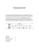

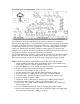


Rear panel connectors
An analog source is fed to the input connectors. There are two sets, selectable by the ‘IN
1-2’ switch on the front panel. This makes it easy to have a D/A normaled to the first
input and the second input wired to a patchbay or tape machine.
The inserts are to include analog processing equipment. It has been found by the authors
after extensive experimentation that 3 insert loops provide the correct number of insert
points verses the minimum number of relays to get the job done. More equipment is
accommodated by ‘ganging’ as explained on the previous page. The insert points can be
run to a patchbay if the added flexibility of patching is needed (to re-route the order of
processing for instance). More connectors and cable may not equal better sound quality.
There are 2 ‘Main outputs’ to feed A/D converters, a tape machine, or patchbay
depending on the user’s preference. The authors use 2 different A/D converters to select
the best one for ‘flavor’ depending on the program material.
The ‘Monitor’ output feeds the Dangerous Music Monitor. The input signal (post Input
level and Input Monitor Offset level controls) or the output signal (post processing) will
be sent to the Monitor depending on the position of the ‘Mon Out’ switch on the front
panel.
The ‘AC IN’ connector goes to the power supply. Please check that the supply is off
before plugging in this cable. Hot plugging will result in burned contacts.
The ‘CHASSIS’ and ‘GROUND’ banana jacks are strapped together at the factory. The
strap may be removed to isolate the chassis and audio grounds. The jacks can be used to
quiet down a troublesome piece of audio equipment (Sontec) with a ground wire if
necessary.