
Manual

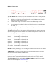


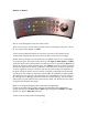
Table Of Contents

SR rear panel
The ‘D’ connectors use the same pin configuration as on the previous page. When the SR
is combined with the ST, 2 ribbon cables are connected between them using the ‘To
Monitor ST’ and ‘From Monitor ST’ jacks. The remote is plugged into the Remote In
jack and a short jumper is run from the Remote Thru to the Remote In jack on the ST
unit. The ST then becomes the controller for the left and right front channels in a 5.1
surround system. The other connectors are:
Inputs 1-4
Signal channel
Left Front 1
Right Front 2
Left Rear 3
Right Rear 4
Center 5
LFE 6
Channels 7&8 are unused.
Speaker 1&2 use the same configuration. The SR can accommodate up to 2 surround
speaker sets this way.
Speaker 3/Sub
Signal channel
Left Front 1
Right Front 2
open 3
open 4
open 5
Sub/LFE mono 6
Sub/LFE left 7
Sub/LFE right 8
The 3
rd
speaker output has a stereo feed for the front channels and a unique feature to
switch signals for the subwoofers in the system. In Stereo mode, the Sub feeds get their
signal from the front channels, output 6 having a mono combiner for systems with one
subwoofer. In surround, the Sub/LFE outputs send the LFE channel signal to the subs.
This facilitates easy accommodation of systems with one or two subwoofers and
combined with the roll-off function and level offsets on the ST, allows easy setup of
signal assignment, realizing the full potential of various speaker setups.
The selected input feeds the Meter Feed jack, channels 1-6.
-7-