Flowlight Booster Pump ® and Solar Slowpump ™ Installation & Service Manual © 2003 by Dankoff Solar Products __________________________________________________________________________ IMPROPER INSTALLATION WILL DAMAGE YOUR PUMP AND VOID YOUR WARRANTY This manual is based on 20 years of experience with over 5000 pumps sold. We are pleased to observe how few problems arise when our pumps are properly installed and maintained.
BASIC CONSTRAINTS I. PUMP MUST NOT BE SUBMERSED II. WATER MUST BE FILTERED ABSOLUTELY CLEAN III. PUMP MUST NOT RUN DRY I. NON-SUBMERSIBLE PUMPS Your pump must NOT be submerged in water, or rained or dripped on. If it is installed outdoors, supply some weather protection, such as a sheet-metal shield or even a dog house – something to keep it dry and also to protect it from the sun’s heat. II. FILTRATION REQUIREMENT Your pump is a PRECISION MACHINE.
III. PUMP MUST NOT RUN DRY Water is the lubricant for your pump. If it runs completely dry, it will overheat and fail. DRY RUN SWITCH is an optional accessory to prevent damage from dry run. It is a small device with two wires that attaches to the front of the pump. It senses temperature, and switches the pump off before it gets too hot. If you are pumping from a tank, cistern or any water source that can run low accidentally, a Dry Run Switch should be used.
INTAKE PIPE MUST BE SIZED GENEROUSLY to allow no more than a slight pressure drop at peak flow rate, or pump will be noisey and will wear rapidly. USE PIPE REDUCER FITTINGS to adapt your pump's inlet or outlet to larger pipe size where necessary. Excessive pipe sizing will do no harm! INTAKE MUST NOT BE RESTRICTED by undersized pipe, excessive suction lift, or a CLOGGED FILTER. Excessive suction at the pump intake causes CAVITATION (formation and implosion of vapor bubbles).
MOUNTING YOUR PUMP Locate your pump in a cool place. Do not allow direct exposure to sunshine during operation, or the motor may overheat. Allow free flow of air around the motor for cooling. SHELTER IT FROM RAIN AND SUN, or it will be a mess in a few years. The pump may be mounted horizontally or vertically. If vertically, FACE THE PUMP HEAD DOWNWARD. RIGID MOUNTING IS NOT required in most installations. In a non-battery system, starting is gradual and the pump does not jerk with the start.
primed. A "pitless adapter" may be optimum for freeze protection. Check with your local well supplier for details. POLYETHYLENE PIPE comes in rolls, and is inexpensive and quite freeze-tolerant. Use with plastic adapters and secure with ALL-STAINLESS hose clamps (obtain such clamps from a pipe supplier rather than automotive supplier). If pipe does not stretch tightly over fittings, warm it with a torch or hot water then tighten clamps firmly with a wrench. Use two clamps at each joint.
Install the fuse or breaker at the power source, to protect the wiring as well as the motor. If the circuit is protected by a breaker, then any additional fuse may be installed at the motor. THERMAL OVERLOAD If your pump resembles the illustration on P.1, a THERMAL SWITCH is mounted on the rear of the motor (inside the white cap) to shut off the motor if it approaches an overheat condition. If this happens, it will turn back on after a cooling period of about 20 minutes.
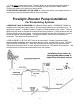
(3) Float valve in tank restricts flow. Pressure builds up and actuates pressure switch at pump. Small captive-air pressure tank is necessary at pump to prevent "switch chatter". Contact your dealer or the factory for further advice. FLOW RESTRICTION MUST NOT BE USED as a method to reduce your pump's flow rate. It may result in excessive pressure build-up and current draw. Flowlight Booster Pump Installation ® For Pressurizing Systems A PRESSURE TANK IS REQUIRED with a Booster Pump system.
NOTE: It is preferable to place the pump LOWER than the water level in the tank. This illustrates an alternative, not an ideal. Note the upward rise of the suction pipe, the high position of the priming plug, and the horizontal position of the filter. These measures help prevent air entrapment that restricts flow and causes pump noise. Follow your pressure switch instructions for wiring. Use the flexible hose that comes with your Booster Pump (cut it into two sections).
If you are raising water vertically AND pressurizing, note the relationship: 2.31 ft. = 1 PSI. Example: A pump that lifts 23 vertical feet and pressurizes to 30 PSI must pump a total of 40 PSI. Total lift = vertical distance from water surface to pressure tank. WARNING: INSTALL THE PRESSURE RELIEF VALVE INCLUDED WITH YOUR PUMP! Flowlight Booster Pumps are supplied with a 75 PSI Pressure Relief Valve as a safety feature.
SOLAR SLOWPUMP — POWER CONTROL for ARRAY-DIRECT (NON-BATTERY) OPERATION When working against a constant head (vertical lift) Solar Slowpump requires nearly constant current, regardless of the voltage/speed. When low light conditions are present, the PV array cannot supply full current. The voltage will drop to nearly zero, and the pump will “stall” (like a truck trying to start in 4th gear). The remedy is either to add a PUMP CONTROLLER, also called LINEAR CURRENT BOOSTER (LCB) to your system.
WATER USAGE WATER CONSERVATION = ENERGY CONSERVATION + LESS FILTER MAINTENANCE TOILETS: A 1.6-gallon flush toilet may reduce total domestic water consumption by 50% compared with typical 4-5 gallon toilets. They are now standard in U.S.A. IRRIGATION SYSTEMS: Many drip, trickle or flood irrigation systems will function on LOW PRESSURE. It is wasteful of energy to supply pressurized water where it is not required.
MAINTENANCE INTERNAL INTAKE SCREEN: The pump has an internal metal intake screen. It's purpose is to catch solids accidently introduced during installation or filter servicing, dirt stuck inside your intake pipe before installation, or mineral deposits that may accumulate and flake off of the intake piping. 1300-SERIES "SLOWPUMP" has an angled extension with a large brass nut on the end. Remove the nut to inspect and empty screen.
TROUBLESHOOTING BEFORE YOU CALL FOR HELP, TRY TO LOCATE YOUR PROBLEM HERE: Please note the terms “Front” and “Rear” -- See P. 1 illustration PUMP WILL NOT FIT INTO YOUR 6" DRILLED WELL CASING: Close Elbow fittings are required (Dankoff Solar Item #20308). PUMP DOESN'T TURN ON -- NO POWER: (1) CHECK DRY RUN SWITCH on front of pump, if present. Press red button to reset. Correct the cause of dry run. (2) CHECK FUSE or BREAKER and any control or wiring devices in line.
to get out of the way of flow. Do NOT turn it upside-down, or dirt may fall in when filter is changed. NOISE AND VIBRATION IN PIPES (pressure gauge vibrates extremely): One of four vanes in the pump is broken. Pump head must be rebuilt -- See Rebuild/Exchange Service. There should be almost no vibration of pressure gauge needle. FILTER CLOGS FREQUENTLY: (1) INTAKE TOO CLOSE to bottom of well, stream, tank etc. Raise it as high as feasible to reduce intake of dirt.
PUMP CYCLES ON AND OFF ABOUT EVERY 20 MINUTES: MOTOR IS OVERHEATING. Thermal switch on back of motor is working. (1) HIGH CURRENT DRAW: See above. (2) NO VENTILATION: Motor must have FREE AIR FLOW to prevent overheating. Do not wrap with insulation. (4) Motor is exposed to sun or other heat source -- keep it cool. (5) BAD THERMAL SWITCH: Motor should shut off at approximately 140 degrees F.
motor repair shop or bearing supplier. Rough commutator must be turned (resurfaced) on a lathe. This may be done by a machine shop or electric motor shop. CORRECT THE CAUSE of damage. If your water level is too unstable, contact your dealer or factory about a submersible pump. RUSTY BEARINGS: (1) PUMP HEAD: Steel ball bearing is visible at pump head shaft. Rust caused by water drip or submersion. Pump head must be rebuilt to replace the bearing (see Rebuild/Exchange).
FACTORY REPAIRS WHEN CALLING FACTORY OR DEALER FOR HELP, PLEASE tell us your MODEL and SERIAL NUMBERS ! Most failures involve the pump head, not the motor. This is the brass part that the pipes connect to. The pump head may be replaced with simple hand tools (a 7/16” wrench and a 1/8” Allen wrench/hex key). YOUR PUMP HEAD IS NOT USER-SERVICEABLE. It is delicate and difficult to re-assemble. Disassembly of your pump head will void your warranty. Individual parts are not available.
Explanation: The National Electrical Code® specifies that switches not disconnect the “grounded conductor”, which is the negative. So, we are switching only the positive. Using both sets of contacts as shown (in series) will extinguish the arc (spark) that forms when the contacts break. This greatly increases switch reliability.
Other solar and DC water pumps ———————————————— SUBMERSIBLE PUMPS FOR SURFACE AND DEEP WATER LIFT AND PRESSURIZING ETAPUMP® SOLAR SUBMERSIBLE 32 GPM at 25 FEET 1.
INDEX Topic Page Diagrams Booster Pump system Check valve Circuit breaker Dry Run Switch Easy installation kit Factory service Filter, cartridges Filter, inline Filter, intake Filter, maintenance Float Switch Freeze protection Fuse protection Grounding Linear Current Booster Maintenance Motor brushes Mounting pump Mounting, suspended in well Noise problems Piping, intake sizing & layout Piping, material Piping, outlet Pressure relief valve (Booster) Pressure Switch Pressure switch adjustment Pressure swi
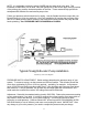
WARNINGS TO INSTALLER 1. This pump pulls water in by suction. The suction pipe must offer a very free flow, like a drain pipe in reverse. The pump will be very noisy if intake is restricted or blocked by air pockets. See Page 3 2. This pump tolerates NO solid debris. A disposable-cartridge filter is required at the intake. NEVER run the pump without a filter. See Page 2 3. Low voltage systems require larger wire than 115V. See Page 6 4. Do not omit the intake screen.
Notes to Installer: Air vent This pump pulls water in by suction. The inlet plumbing must offer a very free flow, like a drain pipe in reverse. The pump will be very noisy if intake is restricted or blocked by air pockets or being undersized. See Page 3 NOISE = CAVITATION = RAPID PUMP WEAR FIX THE PROBLEM!!! See Page 14 This pump tolerates NO solid debris. A disposable cartridge filter is required at the intake. NEVER run this pump without a filter.
Notes to Installer: This pump pulls water in by suction. The inlet plumbing must offer a very free flow, like a drain pipe in reverse. The pump will be very noisy if intake is restricted or blocked by air pockets or being undersized. See Page 3 Module wiring detail is for illustration purposes ONLY. Your array wiring will be different. Consult with your dealer for details NOISE = CAVITATION = RAPID PUMP WEAR FIX THE PROBLEM!!! See Page 14 This pump tolerates NO solid debris.