
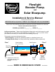
Flowlight Booster Pump Instruction Manual

7
Install the fuse or breaker at the power source, to protect the wiring as well as the motor. If the
circuit is protected by a breaker, then any additional fuse may be installed at the motor.
THERMAL OVERLOAD
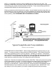
If your pump resembles the illustration on P.1, a THERMAL SWITCH is mounted on the rear of
the motor (inside the white cap) to shut off the motor if it approaches an overheat condition. If
this happens, it will turn back on after a cooling period of about 20 minutes. If overheating
occurs during normal operation of the pump, it may be because it is working beyond it’s
capacity. See Troubleshooting.
The Flowlight Booster Pump, Standard Model may overheat if it is running for more than 20
minutes at a pressure exceeding 50 PSI. It will cool and reset automatically.
GROUNDING and LIGHTNING PROTECTION:
A long wire run may act like an antenna, receiving induced surges of high voltage when lightning
is present. Proper grounding will greatly reduce risk of lightning damage to your power system.
A proper ground system consists of a minimum of one 8 ft. copper-plated ground rod driven into
the ground, preferably in a moist spot close to the PV array. Or, if you have a steel well casing,
drill and tap a bolt hold to make good contact to it.
In a dry, lightning-prone location, use more than one ground rod at least 10 ft. apart. Bury bare
copper wire between them. Use min. #8 ground wire (larger for distances exceeding 20 ft.). In
a rocky location, where ground rods can't be driven, bury (as much as feasible) 150 feet (total)
of bare copper wire, radiating out in two or more directions from the PV array. Try to contact
moist earth as much as possible. Use only the copper or bronze electrical connectors designed
for grounding application, and BE SURE ALL CONNECTIONS ARE TIGHT.
Connect your ground system to the METALLIC FRAME of your PV array via min. #8 copper
wire. Also ground metallic support structures and electrical enclosures. For non-battery pumps,
we have observed the least lightning damage where only the mechanical structure is grounded -
- NOT an electrical conductor. This may vary from electrical codes. Call the manufacturer of
your controller, if you have questions.
WATER LEVEL & FLOW CONTROL
FLOAT SWITCHES/WATER LEVEL SENSORS: These are devices that sense high or low
water level and switch your pump on and off. Ask your dealer or factory about these. Most
switches rated for 15 AMPS at 230 VAC are fine for your DC pump.
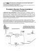
FLOAT CONTROL IN WATER SOURCE may be used if dropping water level is causing dry run
or excessive suction (noise due to cavitation).
FLOAT CONTROL IN STORAGE TANK may be used to turn pump off when tank fills. This
eliminates tank overflow and reduces pump wear and filter changing.
REMOTE FLOAT CONTROL when tank is a LONG DISTANCE from pump may be done in
three ways:
(1) Small wire buried from tank/float switch to pump actuates a relay at the pump.
(2) Very small wire from sensor in tank actuates "Water Level Sensor" option in your pump
controller (LCB). This is for non-battery systems only.