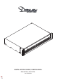
INSTALLATION GUIDE / USER MANUAL DSA500X4 • DSA750X4 Rev.
Technical and Safety Notices Please read the following important technical, safety and environmental notices before installing and using your amplifier. Technical Notices All reasonable design and engineering steps have been taken to ensure that these amplifiers always perform satisfactorily in their intended application and environment and will provide appropriate levels of support to ensure that all reasonable customer needs and expectations are met.
Technical and Safety Notices Important Safety Instructions Environmental Statement 1. 2. 3. 4. 5. 6. 7. This product complies with international directives, including but not limited to the Restriction of Hazardous Substances (RoHS) in electrical and electronic equipment, the Registration, Evaluation, Authorization and restriction of Chemicals (REACH) and the disposal of Waste Electrical and Electronic Equipment (WEEE).
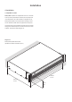
Introduction and Overview 1. Introduction 2. Amplifier Overview Danley DSA power amplifiers have been designed to provide configurable, consistent and reliable high performance audio power amplification for residential, commercial and entertainment applications. Danley DSA500X4 and DSA750X4 amplifiers are a full rack width, 2U format power amplifiers that can drive both conventional low impedance (Lo-Z, 4Ω to 16Ω) loudspeakers and high impedance (Hi-Z, 70V/100V) transformer coupled loudspeakers.
Introduction and Overview 2.1 Connections and Power Switching 3. Carton Contents Danley DSA signal input and output connections are accomplished via RCA Phono and Euroblock style connectors. A GPIO (General Purpose In/Out) Euroblock connector enables some amplifier functions to be controlled externally, and wireless or RJ45 socket Ethernet network connection options are also provided.
Installation 4. Installation 4.1 Amplifier Location Danley DSA amplifiers are shipped with rack “ears” attached and are primarily intended for standard (19 inch) equipment rack installation. If not to be installed in an equipment rack, Danley DSA amplifiers can be placed free-standing on a flat surface. Adhesive rubber feet are supplied for this purpose. It is important that any installation provides space for airflow through the ventilation apertures at the front and rear of the amplifier.
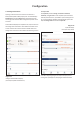
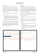
Configuration 5. Configuration Before making input, output and GPIO connections, an initial Danley DSA amplifier configuration should be established. It is particularly important that the amplifier output format is configured appropriately for the speakers that are to be connected. http://192.168.64.100. The Control Web App interface will open to enable amplifier configuration as required.
Configuration 5.3 Configuration Menus 5.3.1 Input Tab Opening a web browser that is network connected to a Danley DSA amplifier initially displays the Control Web App Dashboard illustrated in Diagram 5a. The Dashboard is the ‘home’ page from which all other configuration options can be accessed. The Input Tab provides naming, mono/stereo selection, sensitivity, and gain trim for each amplifier input channel.
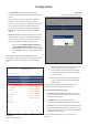
Configuration 5.3.2 Zone Tab 5.3.3 Output Tab The Zone Tab enables installation zones to be defined and named, and provides access to further sub-menus. Zones might be bar or restaurant areas for example, or different rooms in a home. For all Zone Tab menus, the installation zone under configuration is selected by highlighting one of the zone identifiers (A, B, C or D) at the top of the page. Diagram 5c illustrates the Zone Tab.
Configuration • The Speaker Preset menu enables a set of speaker parameters to be adjusted, and preset configurations to be created. Diagram 5f Speaker Preset import file selection • Speaker Presets can be simply applied to the selected amplifier output or imported, chosen from a library, exported or cleared. The preset configurations can include any or all of the parameters described in Section 5.3.4 and can be locked to prevent inadvertent modification.
Configuration Diagram 5g Speaker Preset applied • The Driver Alignment preset menu enables delay to be applied to individual amplifier outputs. • The Polarity preset menu enables the polarity of individual amplifier outputs to be reversed. • The Limiter preset menu enables signal limiting to be applied to individual amplifier outputs. Clip limiting, peak limiting and RMS limiting can be individually or collectively engaged. The Peak limiter can be set to either automatic or custom parameter values.
Configuration 5.3.5 Settings Tab The Settings Tab enables miscellaneous amplifier settings to be configured and installation data to be recorded. The Settings Tab provides access to further sub-menus. Diagram 5i illustrates the Settings Tab. • The System Information menu provides text fields for the recording of installation data. • The Device menu records amplifier specific information such as the model number and firmware version.
Input Gain Input Gain Input Sensitivity Input Sensitivity Gain SPDIF Out (stereo).
Configuration 5.4.1 Input Setup 5.4.2 Zone Setup & Routing Open the configuration Dashboard and select the Input Tab. The Input Tab is shown in Diagram 5b. Open the configuration Dashboard and select the Zone Tab. The Zone Tab is shown in Diagram 5c. • To edit default input names simply select and type in the Input Name field. • Select the zone to be configured.
Configuration 5.5 GPIO Setup and Connection Diagram 5l GPIO Settings Menu Danley DSA amplifiers provide a GPIO socket that enables remote control of volume, standby, mute and trigger functions. The GPIO connector pin functions are described in the GPIO Settings menu illustrated in Diagram 5l. The connection of GPIO based remote volume control and standby/mute are illustrated in Diagram 5m and Diagram 5n respectively. Note: The GPIO connector must not be used for any unintended purpose.
Connections 6. Connections Digital Inputs Danley DSA amplifier rear panel connections are illustrated in Diagrams 6a. Danley DSA S/PDIF stereo digital audio input connections are made via a single RCA Phono socket. The S/PDIF input is connected by default to amplifier installation Zones A (left) and B (right). 6.1 Mains Power Connection Danley DSA amplifiers incorporate a power factor corrected universal power supply and can be used with mains input voltage from 100V AC to 240V AC, 50/60Hz.
Connections 6.4 Speaker Cable Gauge Danley DSA speaker connection cable gauge should be chosen appropriately to reflect the type of installation. The adjacent tables specify the appropriate cable gauge and maximum cable length for less than 0.5dB cable loss in Lo-Z mode and less than 1.0dB cable loss in Hi-Z mode. 6.5 GPIO Connections If any Danley DSA GPIO functionality is required, cables will need to be connected to the supplied GPIO connector.
Connections Diagram 6b Balanced analog input cable connections. 5 mm Low-Z Mode Diagram 6c Output cable connections.
Connections Diagram 6d GPIO cable connections. 5 mm The exclamation point printed next to the output terminals of the amplifiers is, in addition to the CLASS 2 WIRING text, intended to alert users to the risk of hazardous voltages. Output connectors that could pose a risk are marked with the exclamation point. Do not touch the output terminals while the amplifier is switched on. Make all connections with the amplifier switched off.
Operation 7. Operation 7.2 Default Reset Once all connections have been made and configuration options selected, Danley DSA amplifiers are ready for use. If an input signal above -60dB is present on any input, the front panel Input and Standby indicators will illuminate green to indicate normal amplifier operation. Audio will be heard from any connected speakers.
Specifications Model DSA500X4 DSA750X4 4 x Lo-Z/2 x Hi-Z 4 x Lo-Z/2 x Hi-Z Output Power @ 2Ω 4 x 500 W (SE) 4 x 750 W (SE) Output Power @ 4Ω 4 x 500 W (SE) 2 x 1000 W (BTL) 4 x 750 W (SE) 2 x 1500 W (BTL) Output Power @ 8Ω 4 x 250 W (SE) 2 x 1000 W (BTL) 4 x 400 W (SE) 2 x 1500 W (BTL) Output Power @ 70V 2 x 1000 W (BTL) 2 x 1200 W (BTL) Output Power @ 100V 2 x 1000 W (BTL) 2 x 1500 W (BTL) Total System Power 2000 W 3000 W Power Consumption 700 W 700 W 65 Vp / 130 Vpp (SE unloaded)