Dannmar Equipment 646 Flinn Avenue, Suite A Moorpark, CA 93021 Tel: 1-877-432-6627 www.dannmar.com Dannmar R EQUIPMENT D-10 SERIES USER MANUAL Model: D-10/AC D-10/ACX TWO POST LIFT ASYMMETRICAL 10,000 POUND CAPACITY Model: D-10/CX TWO POST LIFT SYMMETRICAL 10,000 POUND CAPACITY Rev D 06012016 P/N# 199824 Reference ANSI/ALI ALIOM safety requirments for installation and service of automotive lifts before installing lift.
TABLE OF CONTENTS IMPORTANT NOTICE ...........................................................................................................................................3 DEFINITIONS OF HAZARD LEVELS .......................................................................................................3 IMPORTANT SAFETY INSTRUCTIONS .......................................................................................................4 OWNER / EMPLOYER RESPONSIBILITIES .............................
IMPORTANT NOTICE 1. Read this manual thoroughly before installing, operating, or maintaining this lift. 2. This lift is designed for indoor use only, and should not be installed in a pit or depression. 3. The floor on which the lift is to be installed must be 4-inch minimum thickness concrete, with a minimum compressive strength of 3000 psi, and reinforced with steel bar. 4. The lifts have specific electrical requirements as described in the Installation Instructions section of this manual. 5.
IMPORTANT SAFETY INSTRUCTIONS READ THESE SAFETY INSTRUCTIONS ENTIRELY! IMPORTANT NOTICE ! Do not attempt to install this lift if you have never been trained on basic automotive lift installation procedures. Never attempt to lift components without proper lifting tools such as forklift or cranes stay clear of any moving parts that can fall and cause injury. 1. READ ALL INSTRUCTIONS. 2. READ AND UNDERSTAND all safety warning procedures before operating lift. 3. KEEP AREA WELL LIT. 4.
21. ONLY TRAINED OPERATORS should operate this lift. All non trained personnel should be kept away from work area. Never let non trained personnel come in contact with, or operate lift. 22. USE LIFT CORRECTLY. Use lift in the proper manner. Never use lifting adapters other than what is approved by the manufacturer. 23. DO NOT override self closing lift controls. 24. REMAIN CLEAR of lift when raising or lowering vehicle. 25. CLEAR AREA if vehicle is on danger of falling. 26.
SAVE THESE INSTRUCTIONS OWNER / EMPLOYER RESPONSIBILITIES • Shall ensure that lift operators are qualified and that they are trained in the safe use and operation of the lift using the manufacturer’s operating instructions; ALI/SM10-1, ALI Lifting it Right safety manual; ALI/ST-10 ALI Safety Tips card; ANSI/ALI ALOIM-2008, American National Standard for Automotive Lifts Safety Requirements for Operation, Inspection and Maintenance; ALI/WL Series, ALI Uniform Warning Label Decals/Placards; and in the case o
• I will assume full responsibility for the concrete floor and condition thereof, now or later, where the above equipment model(s) are to be installed. Failure to follow danger, warning, and caution instructions may lead to serious personal injury or death to operator or bystander or damage to property. • I understand that Dannmar lifts are designed to be installed in indoor locations only.
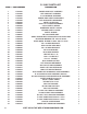
D-10/AC PARTS LIST ITEM # PART NUMBER 1 2 3 4 5 6 7 8 9 10 11 12 13 14 15 16 17 18 19 20 21 22 23 24 25 26 27 28 29 30 31 32 33 34 35 36 37 38 39 40 41 42 43 44 8 17101001 17101003 17102001 17107003 17107004 17204003 17250001 17203002 17108034 17108035 17108036 17300001 17206001 17206002 17206003 17200003 17200004 17200005 17202002 17202003 17201001 17201002 17201003 17204002 17107005 17107006 17108041 17108042 17106001 17106002 17106003 17108044 17207007 17201004 17202005 17201005 17202006 17104001 17103
D-10/AC ASSEMBLY DIAGRAM *Diagram shown with square lift pads. New models come standard with round lift pads. Please note: All Dannmar lifts now come standard with round lift pads for greater durablitly. Call for more information.
D-10/ACX PARTS LIST ITEM # PART NUMBER DESCRIPTION QTY.
D-10/ACX ASSEMBLY DIAGRAM *Diagram shown with square lift pads. New models come standard with round lift pads. Please note: All Dannmar lifts now come standard with round lift pads for greater durablitly. Call for more information.
D-10/CX PARTS LIST ITEM # PART NUMBER 1 2 3 4 5 6 7 8 9 10 11 12 13 14 15 16 17 18 19 20 21 22 23 24 25 26 27 28 29 30 31 32 33 34 35 36 37 38 39 40 41 42 12 17101001 17101003 17104007 17102001 17107003 17107004 17204003 17250001 17203002 17108034 17108035 17108036 17300001 17206001 17206002 17206003 17200003 17200004 17200005 17202002 17202003 17201001 17201002 17201003 17204002 17103010 17107005 17107006 17108041 17108042 17106001 17106002 17106004 17105004 17108085 17207007 17201004 17202005 17201005 1
D-10/CX ASSEMBLY DIAGRAM FOR TECHNICAL QUESTIONS, CALL (877)432-6627 *Diagram shown with square lift pads. New models come standard with round lift pads. Please note: All Dannmar lifts now come standard with round lift pads for greater durablitly. Call for more information.
INSTALLATION INSTRUCTIONS TOOLS REQUIRED Rotary Hammer Drill Or Similar (If Anchoring) 3/4” Masonry Bit (If Anchoring) Hammer 4 Foot Level Open End Wrench Set: Metric Socket And Ratchet Set: Metric Hex Key / Metric Allen Wrench Set Large Crescent Wrench Large Pipe Wrench Crow Bar Chalk Line Medium Flat Screwdriver Tape Measure : 25 Foot Minimum Needle Nose Pliers IMPORTANT NOTICE! These instructions must be followed to ensure proper installation and operation of your lift.
CONCRETE SPECIFICATIONS 10,000-lb 2-Post Lift Models Require 4-inch Min. Thickness / 3,000 PSI Steel Reinforced. IMPORTANT NOTE: All models MUST be installed on 3,000 PSI concrete only conforming to the minimum requirements shown above. New concrete must be adequately cured by at least 28 days minimum.
STEP 4 (Site Layout) 1. Determine which side will be the approach side. 2. Now determine where the power unit will be located. The POWERSIDE column has the power unit mounting bracket attached to the side. Please note, on the Asymmetric model lifts the POWERSIDE column will always be located on the passenger side of the vehicle. 3. Once a location is determined, use a carpenters chalk line to layout a grid for the post locations.
STEP 5 (Install Powerside Column) 1. Before proceeding, double check measurements and make certain that the bases of each column are square and aligned with the chalk line. 2. Using the base plate on the column as a guide, drill each anchor hole in the concrete approximately 4-1/2" deep using a rotary hammer drill and 3/4" concrete drill. To assure full holding power, do not ream the hole or allow drill to wobble. (See figure 5 ) 3.
STEP 6 (Mounting The Offside Column) 1. Position the offside column at the designated chalk locations and secure to the floor following the same procedures as outlined in STEP FIVE; Items 1-6. STEP 7 (Mounting the Top Trough Assembly) 1. Remove all of the equalizer pulleys from the top trough assembly in preparation of installing it to the top of the columns. 2. Using a lifting device, raise the top trough assembly into position on top of the columns.
WARNING You MUST reinstall the top carriage stop bolt (shown below) after the top trough is installed and secured. Tighten the carriage stop bolt to 2-3 ft lb of torque upon final installation inspection. These instruc-tions must be followed to insure proper installation and operation of your lift. Failure to comply with these instructions can result in serious bodily injury and or death and or void product warranty.
STEP 8 (Mounting the Power Unit) 1. Attach the power unit and vibration pad to the powerside column using four M8 x 25mm hex bolts and nylock nuts supplied. (See figure 9) Fig: 9 2. Fill the reservoir with 12 quarts of Aw-32 hydraulic oil or Dexron III or VI transmission fluid. Be sure to use a clean funnel. Step 9 (Installing the Safety System) 1. Install safety weldments into each respective column. (See figure 10 & 11) 2.
Fig: 13 Fig: 12 NOTE: Pulley plate removed for clarity. Fig: 14 Fig: 15 NOTE: Pulley plate removed for clarity. NOTE: Make sure to tighten both nuts equally so as to keep the safety cable centered. DANGER ENSURE THAT BOTH THE POWERSIDE & OFFSIDE SAFETIES ENGAGE PROPERLY PRIOR TO LIFT OPERATION. STEP 10 (Installing Hydraulic Lines) 1. Install the bulkhead tee fitting into the powerside column. The through hole is located approximately 90 inches from the floor on the back wall of the powerside column.
Crossover hose Fig: 16 Fig: 17 Bulkhead fitting Powerside hose Shown with breakout to show bulkhead welded inside each column. Make sure that the hose is clear of any moving parts. It may be necessary to tie the hose clear by using nylon tie straps or wire. (See figure 17) Retaining ring STEP 11 (Routing the Equalizer Cables) Refer to the illustration on page 22 1. Raise and lock each carriage approximately 28” above the ground. 2.
WARNING When the cable adjusting nuts bottom out on the threaded end of the cable connector and there is still slack in the cables, the cables have stretched beyond the safe useful length and need to be replaced with factory approved cable assemblies. Do not place washers, spacers or other devices to shorten the effective cable length as damage to the lift or injury to persons may occur. EQUALIZER CABLE ROUTING NOTE: On the “CX” model both equalizer cables are the same length.
STEP 12 (Attaching The Power Unit Hose) WARNING The power unit hydraulic hose assembly must be routed through the clips in powerside safety cover. Failure to do so can result in personal injury or damage to the Fig: 20 lift. 1. With powerside safety cover loosely positioned route power unit hydraulic hose through clips in powerside safety cover. (See figure 20) Shown with breakout to show hose clip 2.
2. Route the cord up through the power side column using the unused slot then up and across the top tough through the hole on the microswitch box. (See figure 25 & 26) CAUTION When routing the microswitch cable it must be run through the clips in the column and top trough. Failure to do so can cause damage to the lift or vehicles. Fig: 25 Fig: 24 Cable clips STEP 14 (Wiring the Power Unit) Fig: 26 1. The standard power unit for your lift is 220 volt, 60HZ, single phase.
• Motor can not run on 50HZ without a physical change in the motor. • Use a separate breaker for each power unit. • Protect each circuit with a time delay fuse or circuit breaker. • For 208-230 volt, single phase, use a 30 amp fuse. • For 208-230 volt, three phase, use a 30 amp fuse. • For 460 volt, three phase, use a 30 amp fuse. WARNING • DO NOT attempt to raise vehicle until a thorough operation check has been completed. WIRING DIAGRAM 26 VISIT US ON THE WEB AT WWW.DANNMAR.
STEP 15 (Installing the Lift Arms) 1. Place the appropriate lift arm assembly in the lift heads. (See figure 27) 2. Install the lift head pins into the lift head and through the holes in the arm assembly. Fig: 27 CX Models 3. Install the snap ring into the groove in the lift head pin on the under side of the lift head. (See figure 28) Approach DANGER The arm restraint gears must be properly positioned and adjusted.
8. Adjust the gear ring on the arm as necessary to ensure smooth operation and solid engagement of all four arm restraint pin assemblies with the arm restraint gear ring. Fig: 30 DANGER Each arm restraint assembly must be inspected and adjusted as needed before each and every time the lift is operated. Do not operate the lift if any of the four arm restraint systems are not functioning properly.
STEP 17 (Start Up) DANGER RISK OF EXPLOSION! This equipment has internal arcing or parts that may spark and should not be exposed to flammable vapors. Motor should not be located in a recessed area or below floor level. NEVER expose motor to rain or other damp environments. DAMAGE TO MOTOR CAUSED BY WATER IS NOT COVERED UNDER WARRANTY. CAUTION During the START UP procedure, observe all operating components and check for proper installation and adjustment.
POST INSTALLATION CHECK OFF Columns are properly shimmed and stable Oil level Anchor bolts are tightened Lubcation of critical components Pivot / sheave pins are properly attached Check for overhead obstructions Carriage stop bolts torqued to 2-3 ft.
STEP 19 (Operational Test Procedure) Fig: 33 ◊ Load vehicle as per diagram below using the ALI lifting points guide provided. ◊ Raise vehicle 6" - 12" from the ground and check for stability. ◊ Visually inspect for leaks and ensure all operating components are secure. ◊ Raise vehicle to the desired locking point and lower the lift on to the lock and relieve hydraulic pressure. ◊ Raise the vehicle off the locks to allow clearance for the safety lock to clear the locking block on the carriage.
STEP 19 OPERATION INSTRUCTIONS LIFT OPERATION SAFETY • DAILY inspect your lift. Never operate if it malfunctions or if it has broken or damaged parts. Use only qualified lift service personnel and genuine Dannmar parts to make repairs. • THOROUGHLY train all employees in use and care of lift, using manufacturer’s instructions and “Lifting It Right” and “Safety Tips” supplied with the lift. • NEVER allow unauthorized or untrained persons to position vehicle or operate lift.
DANGER When lowering the lift PAY CAREFUL ATTENTION that all personnel and objects are kept clear. ALWAYS keep a visual line of site on the lift AT ALL TIMES. ALWAYS make sure that ALL LOCKS are disengaged. If one of the locks inadvertently locks on descent the lift and/or vehicle may disrupt causing personal injury or death. • ALWAYS REMOVE tool trays, stands, etc. before lowering lift. • ALWAYS RELEASE safety locks before attempting to lower lift.
TYPICAL LIFTING POINTS WARNING Make sure vehicle is neither front nor rear heavy. Center of balance should be midway between adapters as shown below. Asymmetric Vehicle Loading Symmetric Vehicle Loading 7. Stop before making contact with vehicle. Check arm restraint pins for engagement. If required, slightly move arm to allow restraint gear and pawl to mesh. DO NOT hammer arm restraint pin down as this will damage the restraint gear teeth. 8. Raise vehicle until tires clear the floor. 9.
11. DO NOT go near or under a raised vehicle if all four adapters are not in secure contact with vehicle at vehicle manufacturer’s recommended lift points. 12. Repeat entire loading and raising procedures if required. 13. Lower lift onto safety locks. DANGER VISUALLY CONFIRM THAT ALL PRIMARY SAFETY LOCKS ARE ENGAGED BEFORE ENTERING WORK AREA. Suspension components us on this lift are intended to raise and lower lift only and are not meant to be load holding devices.
7. NEVER, drive over lift arms. 8. If lift is not operating properly, Do Not use until adjustment or repairs are made by qualified lift service personnel. MAINTENANCE INSTRUCTIONS CAUTION If you are not completely familiar with automotive lift maintenance procedures; STOP: Contact the factory for instructions. To avoid personal injury, permit only Trained Lift Service Personnel to perform maintenance on this equipment. • Always keep bolts tight. Check periodically. • Always keep lift components clean.
REQUIRED MONTHLY MAINTENANCE Check all arm adjusting locks for proper operation. Check all cables connections, bolts and pins to insure proper mounting and torque. Visually inspect safeties for proper operation. Lubricate columns with grease. Inspect all anchors bolts and retighten if necessary. Check all columns for squareness and plumb. Inspect all pivot arms pins making sure they are properly secure. Check equalizer cable tension, and adjust if necessary. 1.
WIRE ROPE INSPECTION AND MAINTENANCE ◊ Lifting cables should be replaced every three - five years or when visible signs of damage are apparent. DO NOT USE LIFT WITH DEFECTIVE / WORN CABLES. ◊ Lifting cables should be maintained in a well lubricated condition at all times. Wire rope is only fully protected when each wire strand is lubricated both internal and external. Excessive wear will shorten the life of the wire rope.
LIFT LOCKOUT / TAGOUT PROCEDURE Purpose: This procedure establishes the minimum requirements for the lockout of energy that could cause injury to personnel by the operation of lifts in need of repair or being serviced. All employees shall comply with this procedure. Responsibility: The responsibility for assuring that this procedure is followed is binding upon all employees and service personnel from outside service companies (i.e., authorized installers, contactors, etc.).
Safe Lift Operation Automotive and truck lifts are critical to the operation and profitability of your business. The safe use of this and other lifts in your shop is critical in preventing employee injuries and dama lifts safely you can insure that your shop is profitable, productive and safe. Safe operation of automotive lifts requires that only trained employees should be allowed to use the lift. TRAINING SHOULD INCLUDE, BUT NOT LIMITED TO: • Proper positioning of the vehicle on the lift arms.
DANGER • DO NOT leave the controls while the lift is still in motion. • DO NOT stand directly in front of the vehicle or in the bay when vehicle is being loaded or driven into position. • DO NOT go near vehicle or attempt to work on the vehicle when being raised or lowered. • REMAIN CLEAR of lift when raising or lowering vehicle. • DO NOT rock the vehicle while on the lift or remove any heavy component from vehicle that may cause excessive weight shift.
TROUBLESHOOTING GUIDE LIFT WILL NOT RAISE POSSIBLE CAUSE 1. Air in oil, (1,2,8,13) 2. Cylinder binding, (9) 3. Cylinder leaks internally, (9) 4. Motor run backward under pressure, (11) 5. Lowering valve leaks, (3,4,6,10,11) 6. Motor runs backwards, (7,14,11) 7. Pump damaged, (10,11) 8. Pump won’t prime, (1,8,13,14,3,12,10,11) 9. Relief valve leaks, (10,11) 10. Voltage to motor incorrect, (7,14,11) REMEDY INSTRUCTION 1. Check for proper oil level.
MOTOR WILL NOT RUN POSSIBLE CAUSE 1. Fuse blown, (5,2,1,3,4) 2. Limit switch burned out, (1,2,3,4) 3. Microswitch burned out, (1,2,3,4) 4. Motor burned out, (1,2,3,4,6) 5. Voltage to motor incorrect, (2,1,8) REMEDY INSTRUCTION 1. Check for correct voltage. Compare supply voltage with voltage on motor name tag. Check that the wire is sized correctly. 2. Check motor is wired correctly. Compare wiring of motor to electrical diagram on drawing. 3. Don’t use extension cords. According to N.E.C.
WILL NOT RAISE LOADED LIFT POSSIBLE CAUSE 1. Air in oil, (1,2,3,4) 2. Cylinder binding, (5) 3. Cylinder leaks internally, (5) 4. Lift overloaded, (6,5) 5. Lowering valve leaks, (7,8,1,5,9) 6. Motor runs backwards, (10,12,9) 7. Pump damaged, (5,9) 8. Pump won’t prime, (1,2,3,4,5,11,9) 9. Relief valve leaks, (8,5,9) 10. Voltage to motor incorrect, (10,12,5) REMEDY INSTRUCTION 1. Check oil level. The oil level should be up to the bleed screw in the reservoir with the lift all the way down. 2.
LIFT WILL NOT STAY UP POSSIBLE CAUSE 1. Air in oil, (1,2,3) 2. Check valve leaks, (6) 3. Cylinders leak internally, (7) 4. Lowering valve leaks, (4,5,1,7,6) 5. Leaking fittings, (8) REMEDY INSTRUCTION 1. Check oil level. The oil level should be up to the bleed screw in the reservoir with the lift all the way down. 2. Oil seal is damaged and cocked. Replace oil seal around pump shaft. 3. Bleed cylinder. 4. Flush release valve. Hold release handle down and start unit allowing it to run for 15 seconds. 5.
MAINTENANCE RECORDS ___________________________________________________________________ ___________________________________________________________________ ___________________________________________________________________ ___________________________________________________________________ ___________________________________________________________________ ___________________________________________________________________ ___________________________________________________________________ _______________
GENERAL DISCLAIMER In addition to all claim s listed on each of the following individual W ARRANTY pages, the following GENERAL DISCLAIMERS apply. 1. The purchaser of any DANNMAR product (Buyer) assum es the risk of verifying all m aterials or resources used or relied on.
DANNMAR Term s and conditions of Sale are to be the com plete and exclusive agreem ent (Agreem ent) between the parties superseding all oral or written prior agreem ents and all other com m unications between the parties relating to the subject m atter of said Agreem ent, including statem ents m ade by sales persons. No em ployee of DANNMAR or any other party is authorized to m ake any warranty in addition to those m ade in the Agreem ent.
LIMITED WARRANTY - TWO-POST LIFTS/FOUR-POST LIFTS Better Products - Better Service - Better Value Duration: From the date of purchase by original Purchaser or 36/12 months from the date of shipment by DANNMAR or whichever comes first. T Three Years (36-Months) Warranty on the lift structure T One Year (12-Months) Warranty on operating com ponents Limited Warranty 1. Who offers this warranty (Warrantor): DANNMAR Inc., 646 Flinn Ave. Moorpark, CA 93021 2.
www.dannmar.com | 877.432.6627 Some other great Dannmar products that may interest you: Dannmar Tripod Stand 2-Ton capacity Minimum height: 68.7" Maximum height: 78.7" Dannmar 8-Gal Oil Drain Minimum height: 48" Max Height: 67" Wide drain pipe drains oil quickly Rolling Work Seat Capacity (each): 250 lbs. / 113.4 kg. Depth: 14.5" / 368.3 mm. Overall Height: 14" / 355.6 mm. Dannmar Round Lift Pad For use with Dannmar 2-Post lifts.
Dannmar R EQUIPMENT FOR PARTS OR SERVICE CONTACT: FOR PARTS OR SERVICE CONTACT: Dannmar Equipment, Inc. 646 Flinn Ave, Suite A Moorpark, CA 93021 Tel: 1-844-629-5291 Fax: 1-805-530-1909 www.dannmar.com ALTHOUGH EVERY EFFORT HAS BEEN TAKEN TO ENSURE COMPLETE AND ACCURATE INSTRUCTIONS HAVE BEEN INCLUDED IN THIS MANUAL, POSSIBLE PRODUCT UPDATES, REVISIONS AND OR CHANGES MAY HAVE OCCURRED SINCE THE PRINTING OF THIS MANUAL.