
Full Product Manual
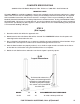


ARM CONFIGURATION
FOR TECHNICAL QUESTIONS, CALL (877)432-6627
17
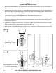
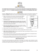
STEP 14
(Installing the Lift Arms)
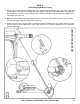
1. Place the lift arm assembly in the lift heads. (See figure 10)
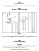
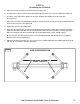
2. Install the lift head pins into the lift head and through the holes in the arm assembly. (See figure 11)
3. Install the snap ring into the groove on the lift head pin in the middle of the lift head tube.
(See figure 11)
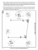
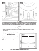
4. Loosen the arm lock assembly bolts and adjust so that the teeth on the gear mesh smoothly with the
teeth on the arm gears. (See figure 12)
5. Tighten the arm lock assembly bolts.
6. Verify the operation of the arm lock assembly by pulling up on the handle of the arm lock assembly.
Pivot the arms back and forth and test the operation of the arm lock assembly in various positions.
When releasing the arm lock assembly the pin should drop and the gears should engage.
7. Ensure that the arms do not move when a force of approximately 100-pounds or less is applied
laterally to the fully extended arms.
8. Adjust the arm lock assembly as necessary to ensure smooth operation and solid engagement of all
four arm lock assemblies with the arm gears.
Fig: 10
MEDIUM ARMS ASSEMBLIES
ITEM # 17103014