Dannmar Equipment 646 Flinn Avenue, Suite A Moorpark, CA 93021 Tel: 1-877-432-6627 www.dannmar.com Dannmar R EQUIPMENT D-7 SERIES USER MANUAL Model: D-7 D-7/X FOUR POST PARKING LIFT 7,000 POUND CAPACITY Also known as Commander 7000 Rev G 06012016 P/N# 199818 Reference ANSI/ALI ALIOM safety requirments for installation and service of automotive lifts before installing lift. PLEASE READ THE ENTIRE CONTENTS OF THIS MANUAL PRIOR TO INSTALLATION AND OPERATION.
TABLE OF CONTENTS PRODUCT SPECIFICATIONS .......................................... 2 IMPORTANT NOTICE ....................................................... 3 DEFINITIONS OF HAZARD LEVELS ............................... 3 IMPORTANT SAFETY INSTRUCTIONS ........................... 4 OWNER/EMPLOYER RESPONSIBILITIES ...................... 6 PRODUCT DIMENSIONS ................................................. 7 INSTALLATION INSTRUCTIONS ......................................
IMPORTANT NOTICE 1. Read this manual thoroughly before installing, operating, or maintaining this lift. 2. This lift is designed for indoor use only, and should not be installed in a pit or depression. 3. The floor on which the lift is to be installed must be 4" inch minimum thickness concrete, with a minimum compressive strength of 3000 PSI, and reinforced with steel bar. 4. The lifts have specific electrical equirements as described in the Installation Instructions section of this manual. 5.
IMPORTANT SAFETY INSTRUCTIONS 1. READ ALL INSTRUCTIONS. 2. CARE MUST BE TAKEN as burns can occur from touching hot parts. 3. DO NOT operate equipment with a damaged power cord or if the equipment has been dropped or damaged until it has been examined by a qualified service person. 4. DO NOT let the power cord come in contact with hot manifolds or moving fan blades. 5. IF AN EXTENSION CORD IS NECESSARY, a cord with a current rating equal to or more than that of the equipment should be used.
22. ALWAYS ENSURE that the safety locks are engaged before any attempt is made to work on or near vehicle. 23. DRESS PROPERLY. Non-skid steel-toe footwear is recommended when operating lift. 24. GUARD AGAINST ELECTRIC SHOCK. This lift must be grounded while in use to protect the operator from electric shock. Never connect the green power cord wire to a live terminal. This is for ground only. 25. DANGER! The power unit used on this lift contains high voltage.
SAVE THESE INSTRUCTIONS OWNER / EMPLOYER RESPONSIBILITIES • Shall ensure that lift operators are qualified and that they are trained in the safe use and operation of the lift using the manufacturer’s operating instructions; ALI/SM10-1, ALI Lifting it Right safety manual; ALI/ST-10 ALI Safety Tips card; ANSI/ALI ALOIM-2008, American National Standard for Automotive Lifts-Safety Requirements for Operation, Inspection and Maintenance; ALI/WL Series, ALI Uniform Warning Label Decals/Placards; and in the case o
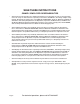
D-7 Page 7 D-7/X
INSTALLATION INSTRUCTIONS TOOLS REQUIRED 1. Rotary Hammer Drill Or Similar (If Anchoring) 2. 3/4” Masonry Bit (If Anchoring) 3. Hammer 4. Foot Level 5. Open End Wrench Set: Metric 6. Socket And Ratchet Set: Metric 7. Hex Key / Metric Allen Wrench Set 8. Medium Crescent Wrench IMPORTANT NOTICE! These instructions must be followed to ensure proper installation and operation of your lift. Failure to comply with these instructions can result in serious bodily harm and void product warranty.
Please note the differences on each side of the posts. The lock blocks extend further out on one side, this side should always face the inside of the lift. “X” Indicates your two options for Power Unit Location (Passenger Rear recommended). STEP 2 (Column & Cross Bar Installation) 1. IMPORTANT! DO NOT begin installation with lift close to wall. It is necessary to leave adequate clearance for installing safety linkage rods.
STEP 3 (Runway Installation) Fig. 5 1. Locate the runway with the cylinder attached underneath. This runway will be located adjacent the column with power unit bracket attached. 2. Position the 1/2" holes on the side of the runway near the power unit location. (See Fig. 5) 3. Line up the front of the cylinder runway with the cross bar bolt holes, then temporarily bolt in position using the M14 x 100mm hex bolt, nut and washers making sure to pass bolts through the front tire stops. (See Fig.
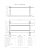
Page 11 For technical questions, please call 877.432.6627 4013mm 6502mm 7925mm Cable “C” Cable “D” Cable “D” 2591mm Cable “A” Cable “B” D-7 Cable “C” 8992mm 3029mm 4464mm 7588mm D-7/X Cable “B” Cable Stop Fig. 1-3 CABLE ROUTING Fig. 1-3 Cable “A” Fig. 1-2 Cable Stop Fig.
STEP 4 (Cable Installation) IMPORTANT! Do not damage the chrome cylinder rod during this process. This can ruin the seals of the cylinder resulting in fluid leakage 1. Inspect cylinder nut and tighten if necessary. Be sure to have at least 4-6 threads past the nylon on the nut. 2. Inspect cables to ensure proper lengths. All cables should have ID tags showing proper cable lengths. (See Table on page 11 for proper lengths.) 3.
sure to point the fitting towa ds the power unit. On the pipe thread side of the fitting use teflon tape or pipe sealer. DO NOT USE TEFLON TAPE on JIC flared end. 5. Install the pneumatic push-to-connect 90-degree fitting at the cylinder port closest to the power unit making sure to point the fitting towards the power unit. On the pipe thread side of the fitting use Teflon tape or pipe sealer. 6.
STEP 7 (Connecting Safety Linkage Rods) Install the Linkage Rods as shown below, making sure to position the Safety Handle adjacent to the Power Unit. Pay careful attention to assemble the FRONT and REAR Linkage assemblies as shown. Improper assembly will result in Safety Lock failure. (See Fig. 10.1, 10.2 on previous page & 10.3 ) Fig. 10.3 Page 14 For technical questions, please call 877.432.
STEP 8 (Inspecting Pulley Guards) 1. After the lift is installed, lightly oil the cable roller shafts with lubrication (gear grease). 2. Before proceeding, double check to make sure the locking shaft collars for the cross bar cable pulleys and pulley guards are tightened securely. DANGER Locking Shaft Collar To prevent personal injury or death, cross bar lock collars must remain tight at all times.
STEP 9 (Anchoring: Optional) Proceed to Step 10 if not anchoring. 1. Concrete shall have compression strength of at least 3,000 PSI and a minimum thickness of 4" in order to achieve a minimum anchor embedment of 3¼". NOTE: When using (¾" x 5½") long anchors; if the top of the anchor exceeds 2¼" above the floor grade, you DO NOT have enough embedment. 2. Maintain a 6" minimum distance from any slab edge or seam. Hole to hole spacing should be a minimum 6½" in any direction.
POST-INSTALLATION CHECK-OFF ; Columns Properly Shimmed And Stable Anchor Bolts Tightened (Optional) ; Pivot / Sheave Pins Properly Attached ; Electric Power Supply Confirmed ; Cables Adjusted Properly ; Safety Locks Functioning Properly ; Slack Cable Safety secure and engaged.
STEP 10 ( Operational Test ) 1. Make sure power unit reservoir is full with 10-qts of AW-32 hydraulic oil or Dexron III or VI ATF. 2. Spray the inside of the columns where the slide blocks glide with a white lithium grease. 3. Press the UP SWITCH on the power unit. 4. The lift will slowly raise. 5. Once the lift starts to raise, simultaneously press the lowering handle at the same time you are pressing the raise button.
IMPORTANT INSTRUCTIONS PLEASE READ! LIFT OPERATION: To Raise Lift: 1. Position vehicle tires in the center of each runway. 2. Set parking brake and use wheel chocks to hold vehicle in position. 3. Before raising the vehicle make sure you replace the drive up ramps with the tire stops, make sure all personnel are clear of the lift and surrounding area. Pay careful attention to overhead clearances. 4. Raise the lift to the desired height by pressing the push button of the power unit. 5.
TO LOWER THE LIFT: 1. First, raise the lift to clear the safety locks. 2. Depress air safety release button and hold. (If not so equipped, release safety locks manually.) 3. Push the lowering handle and hold until the lift has descended completely. 4. If the lift is shaking, vibrating, or swaying, reduce the descending speed. WEEKLY MAINTENANCE: 1. Lubricate all rollers with general purpose lubricating oil. 2. Check all connections, bolts, and pins to ensure proper mounting. 3.
D-7 PARTS LIST ITEM # PART # 1 17051003 2 17051005 3 17051004 4 17052005 5 17052006 6 17057014 7 17057015 8 17058066 9 17058067 10 17204012 11 17202021 12 17057016 13 17058068 14 17058069 15 17058070 16 17200018 17 17300004 18 17207015 19 17206013 20 17206008 21 17206022 22 17201018 24 17057017 24 17057018 25 17207041 26 17201019 27 17058071 28 17058072 30 17058073 30 17207020 31 17250008 32 17058074 Page 21 DESCRIPTION D-7 POWERSIDE POST ASSEMBLY D-7 RIGHT POST ASSEMBLY D-7 LEFT POST ASSEMBLY D-7 POWERSI
D-7 PARTS LIST ITEM # PART # 33 17058075 34 17058076 35 17201020 36 17200005 37 17201010 38 17200025 39 17202022 40 17202023 41 17201021 42 17200030 43 17202005 44 17202001 45 17201004 46 17201007 47 17201023 48 17201022 49 17200031 50 17200032 51 17202006 52 17201005 53 17202011 54 17200033 55 17058077 56 17053010 57 17055005 58 17055006 59 17055007 60 17055008 61 17056002 62 17056004 63 17206031 64 17206010 65 17058265 Page 22 DESCRIPTION CYLINDER BLOCK ASSEMBLY LARGE CYLINDER BLOCK SUPPORT 1-14 NYLON L
D-7 ASSEMBLY DIAGRAM Page 23 For technical questions, please call 877.432.
D-7/X PARTS LIST ITEM # PART # 1 17051007 DESCRIPTION D-7/X POWERSIDE POST ASSEMBLY QTY.
D-7/X PARTS LIST ITEM # PART # 34 35 36 37 38 39 40 41 42 43 44 45 46 47 48 49 50 51 52 53 54 55 56 57 58 59 60 61 62 63 64 65 Page 25 17058075 17058076 17201020 17200005 17201010 17200025 17202022 17202023 17201021 17200030 17202005 17202001 17201004 17201007 17201023 17201022 17200031 17200032 17202006 17201005 17202011 17200033 17058077 17053012 17056006 17055009 17055010 17055011 17055012 17206010 17206031 17058265 DESCRIPTION QTY.
D-7/X ASSEMBLY DIAGRAM Page 26 For technical questions, please call 877.432.
TROUBLESHOOTING GUIDE 1. Power Unit does not raise: 1.1 Verify electrical source matches motor specifications. 1.2 Verify breaker is not tripped or not working. 1.3 Verify correct voltage to motor. 2. The Power Unit runs but will not lift: 2.1 Check oil level. 2.2 Check that the lowering valve is not stuck open. 2.3 Check and verify all hose connections are complete. 3. The power unit raises the lift empty but will not lift a vehicle. 3.1 Make sure the vehicle is not above the rated capacity. 3.
7.3 Check and make sure the platform is level, adjust cables if necessary as described in the Installation Instruction section of this manual. 7.4 Check oil level. 7.5 Make sure there is no air in the system, bleed as described in the Installation Instruction section of this manual. 8. Lift lowers approximately 1" and stops. 8.1 Check and make sure all safety locks are released. 9. At full height the latch will not release and the lift will not lower. 9.
devices for other equipment may be located in close proximity of the appropriate energy isolating device. If the identity of the device is in question, see the shop supervisor for resolution. Ensure that proper authorization is received prior to performing the lockout procedure. Sequence of Lockout Procedure: 1. Notify all affected employees that a lockout is being performed and the reason for it. 2. Unload the subject lift.
PREVENTIVE MAINTENANCE SCHEDULE 1. The periodic Preventive Maintenance Schedule given is the suggested minimum requirements and minimum intervals; accumulated hours or monthly period, which ever comes sooner. 2. Periodic maintenance is to be performed on a daily, weekly, and yearly basis as given in the following paragraphs: 3. In the event you need replacement parts, use only Direct Lift replacement parts available from your local Dannmar Lift distributor. 4.
4. Check and tighten bolts, nuts, and screws. 5. Check all cable sheaves/assembly for free movement or excessive wear on cable sheave shaft. MONTHLY MAINTENANCE: 1. Lubricate the inside of each column with gear grease. 2. With the lift in the lowered position, check the hydraulic fluid level. Add oil if necessary as described in the Installation section of this manual. 3. Check synchronization of all four locks and assure they all click together.
CABLE INSPECTION GUIDE Nom. Cable Diameters 3/8" to 1/2" Max. Reduction in Diameter 1/32" Typical Good Cable Cable with Severe Corrosion Cable with Broken Wires Cable with Nicking Daily Inspection & Maintenance: 1. Cleanliness: Cables, Columns, Runways, and other lift parts should be kept free of corrosive agents, solvents, and road salts. If such agents are spilled or splashed on any lift component, immediately rinse thoroughly with water and wipe down with a clean rag.
excessive noise during operation. 5. Sheave Pins: Check for loose or missing sheave (pulley) pins. 6. Locking Latches and Slack Cable Devices: Watch locking latches and slack cable devices during lift operation to ensure that latches work properly and line up with slots in latch plate located in columns. Monthly Inspection & Maintenance: CABLES: 1. Clean wire rope cables with lift in both lowered and raised position by spraying with penetrating oil and wiping the cable down. 2.
“breakin”, after which small periodic adjustments may be required. However, if a cable that has been in service for 6 months should suddenly require frequent adjustments or has used all the cable adjustment available, all cables must be replaced immediately. 6. If any cable is found to be in need of replacement, the entire cable set must be replaced immediately. 7.
REQUIRED SAFETY LABELS Page 35 For technical questions, please call 877.432.
WARRANTY INFORMATION FOUR POST AUTO LIFT READ THIS ENTIRE MANUAL BEFORE OPERATION BEGINS. This instruction manual has been prepared especially for you. Your new lift is the product of over 25 years of continuous research, testing and development and is the most technically advanced lift on the market today. RECORD HERE THE FOLLOWING INFORMATION WHICH IS LOCATED ON THE SERIAL NUMBER DATA PLATE Serial No. __________ Model No.
LIMITED WARRANTY - TWO-POST LIFTS/FOUR-POST LIFTS Better Products - Better Service - Better Value Duration: From the date of purchase by original Purchaser or 36/12 months from the date of shipment by DANNMAR or whichever comes first. T Three Years (36-Months) Warranty on the lift structure T One Year (12-Months) Warranty on operating com ponents Limited Warranty 1. Who offers this warranty (Warrantor): DANNMAR Inc., 646 Flinn Ave. Moorpark, CA 93021 2.
GENERAL DISCLAIMER In addition to all claim s listed on each of the following individual W ARRANTY pages, the following GENERAL DISCLAIMERS apply. 1. The purchaser of any DANNMAR product (Buyer) assum es the risk of verifying all m aterials or resources used or relied on.
DANNMAR Term s and conditions of Sale are to be the com plete and exclusive agreem ent (Agreem ent) between the parties superseding all oral or written prior agreem ents and all other com m unications between the parties relating to the subject m atter of said Agreem ent, including statem ents m ade by sales persons. No em ployee of DANNMAR or any other party is authorized to m ake any warranty in addition to those m ade in the Agreem ent.
MAINTENANCE RECORDS ___________________________________________________________________ ___________________________________________________________________ ___________________________________________________________________ ___________________________________________________________________ ___________________________________________________________________ ___________________________________________________________________ ___________________________________________________________________ _______________
MAINTENANCE RECORDS ___________________________________________________________________ ___________________________________________________________________ ___________________________________________________________________ ___________________________________________________________________ ___________________________________________________________________ ___________________________________________________________________ ___________________________________________________________________ _______________
www.dannmar.com | 877.432.6627 Some other great Dannmar products that may interest you: Dannmar Tripod Stand 2-Ton capacity Minimum height: 68.7” Maximum height: 78.7” Dannmar 8-Gal Oil Drain Rolling Work Seat Capacity (each): 250 lbs. / 113.4 kg. Depth: 14.5” / 368.3 mm. Overall Height: 14” / 355.6 mm. Dannmar Round Lift Pad Minimum height: 48” Max Height: 67” Wide drain pipe drains oil quickly For use with Dannmar 2-Post lifts. Sold as pad-only or with full assembly.
FOR PARTS OR SERVICE CONTACT: Dannmar Equipment, Inc. 646 Flinn Ave. Suite A Moorpark, CA. 93021 Tel: 877-432-6627 Fax: 805-530-1909 www.dannmar.com ALTHOUGH EVERY EFFORT HAS BEEN TAKEN TO ENSURE COMPLETE AND ACCURATE INSTRUCTIONS HAVE BEEN INCLUDED IN THIS MANUAL, POSSIBLE PRODUCT UPDATES, REVISIONS AND OR CHANGES MAY HAVE OCCURRED SINCE THE PRINTING OF THIS MANUAL. DANNMAR EQUIPMENT RESERVES THE RIGHT TO CHANGE SPECIFICATIONS WITHOUT INCURRING ANY OBLIGATION FOR EQUIPMENT PREVIOUSLY OR SUBSEQUENTLY SOLD.