
Product guide


7
Operation
Installation
Remove all packing materials from the MPA-4250. Check that all foam and plastic padding is removed.
Secure the equipment into a 19" rack. Connect all cables.
Connecting Power / Circuit Size Requirements.
The actual current draw, the amplifier demands from the AC mains, depends on many factors (its load,
output level or the crest factor of its program material).
The power requirement is rated under typical music conditions, with both channels driven so those peaks
are just at the clipping point.
Make sure the mains voltage is correct and is the same as printed on the rear of the amplifier. Damage
caused by connecting the amplifier to improper AC voltage is not covered by any warranty. Unless
otherwise specified when ordered. DAP audio amplifiers shipped to customers are configured as follows:
North America 120VAC/60Hz
Europe 230VAC/50Hz
Asia 220VAC /50Hz/60Hz
Australia 240VAC/50Hz
South America 120VAC/60Hz or 220VAC/50Hz
Japan 100VAC/50Hz
NOTE: Always turn off and disconnect the amplifier from mains voltage before making audio
connections. Also, as an extra precaution, have the attenuators turned down during power-up.
Dip switch settings
The MPA4250 has 4 balanced combo inputs. You can use these for connecting either jack or XLR cables.
Each input can be customized using 4 dipswitches. You can select 4 options:
5. Line/ Mic: Use this switch to set the input impedance/ sensitivity to either Line or Microphone level.
Off position is Line, On position is Mic.
6. Phase: If this switch is in on position, the phase will be inversed.
7. High pass filter: In on position a highpass filter will be activated. The cutoff frequency is 200Hz.
8. 48V phantom power: In on position the input will provide 48V phantom power for a condenser
microphone.
Connecting Inputs.
Use the XLR input connectors on the rear to supply audio signals to your DAP Audio MPA- Series amplifier.
The connectors accept balanced and unbalanced audio connections. (The MPA- Series amplifiers are
configured standard with "Pin 2 hot" on XLR inputs. For more Information, see the section on Connection
cables page 9.
Connecting Outputs.
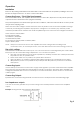
Speakers are connected using terminal connectors. See the examples below and following page.
Low impedance outputs
You can use as many speakers as you want as long as the total impedance matches the amplifiers
output.
Example 1: using the 4Ω output with two 8Ω speakers.
Fig. 3