
Product guide


9
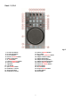
Frontside
Fig. 4
48. Touch sensitivity control jogwheel A 53. Crossfader slope switch
49. Touch sensitivity control jogwheel B 54. Channel 3 input switch
50. Mic input jack 55. Cue mix control
51. Mic volume control 56. Headphone volume control
52. Channel 3 input switch 57. Headphone output jack
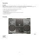
Backside
Fig. 5
58. Power on/off switch 65. Channel 4 line/phono switch
59. DC In 7,5V 2A 66. GND screw
60. USB connector 67. Channel 3 RCA input
61. Master XLR out L/R 68. Channel 3 line/phono switch
62. Master RCA out L/R 69. Channel 4 input level control
63. Booth RCA out L/R 70. Channel 3 input level control
64. Channel 4 RCA input
Installation
Remove all packing materials from the Kontrol D4i. Check that all foam and plastic padding is removed.
Connect all cables.
Always disconnect from electric mains power supply before cleaning or servicing.
Damages caused by non-observance are not subject to warranty.
Set Up and Operation
Before plugging the unit in, always make sure that the power supply matches the product specification
voltage. The power supply demands are printed on the back of the device.
Connections
1. Connect the Kontrol D4i to your mixer/amplifier using the proper cables.
2. Connect the supplied power adapter
CAUTION: Be sure that the mixer/amplifier’s power is off, when connecting the cables. Turn on the Kontrol
D4i before you turn on your mixer/amplifier.