
User manual


Chapter 4 Connecting Signals
© National Instruments Corporation 4-29 NI 6034E/6035E/6036E User Manual
CONVERT* Signal
Any PFI pin can externally input the CONVERT* signal, which is
available as an output on the PFI2/CONVERT* pin.
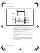
Refer to Figures 4-11 and 4-12 for the relationship of CONVERT* to
the DAQ sequence.
As an input, the CONVERT* signal is configured in the edge-detection
mode. You can select any PFI pin as the source for CONVERT* and
configure the polarity selection for either rising or falling edge. The
selected edge of the CONVERT* signal initiates an A/D conversion.
The ADC switches to hold mode within 60 ns of the selected edge. This
hold-mode delay time is a function of temperature and does not vary from
one conversion to the next. CONVERT* pulses should be separated by at
least 5 µs (200 kHz sample rate).
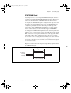
As an output, the CONVERT* signal reflects the actual convert pulse
that is connected to the ADC, even if the conversions are being externally
generated by another PFI. The output is an active low pulse with a pulse
width of 50 to 150 ns. This output is set to tri-state at startup.
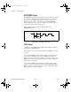
Figures 4-21 and 4-22 show the input and output timing requirements for
the CONVERT* signal.
Figure 4-21. CONVERT* Input Signal Timing
Rising-Edge
Polarity
Falling-Edge
Polarity
t
w
= 10 ns minimum
t
w
UM.book Page 29 Monday, May 14, 2001 10:32 AM