
User manual


Chapter 4 Connecting Signals
© National Instruments Corporation 4-31 NI 6034E/6035E/6036E User Manual
SISOURCE Signal
Any PFI pin can externally input the SISOURCE signal, which is not
available as an output on the I/O connector. The onboard scan interval
counter uses the SISOURCE signal as a clock to time the generation of
the STARTSCAN signal. You must configure the PFI pin you select as
the source for the SISOURCE signal in the level-detection mode. You
can configure the polarity selection for the PFI pin for either active high
or active low.
The maximum allowed frequency is 20 MHz, with a minimum pulse width
of 23 ns high or low. There is no minimum frequency limitation.
Either the 20 MHz or 100 kHz internal timebase generates the SISOURCE
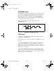
signal unless you select some external source. Figure 4-23 shows the timing
requirements for the SISOURCE signal.
Figure 4-23. SISOURCE Signal Timing
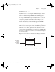
Waveform Generation Timing Connections
The analog group defined for your device is controlled by WFTRIG,
UPDATE*, and UISOURCE.
WFTRIG Signal
Any PFI pin can externally input the WFTRIG signal, which is available as
an output on the PFI6/WFTRIG pin.
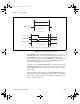
As an input, the WFTRIG signal is configured in the edge-detection mode.
You can select any PFI pin as the source for WFTRIG and configure the
polarity selection for either rising or falling edge. The selected edge of the
WFTRIG signal starts the waveform generation for the DACs. The update
interval (UI) counter is started if you select internally generated UPDATE*.
t
w
= 23 ns minimum
t
p
= 50 ns minimum
t
w
t
w
t
p
UM.book Page 31 Monday, May 14, 2001 10:32 AM