
User manual


Appendix A Device-Specific Information
E Series User Manual A-14 ni.com
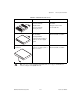
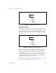
Figure A-8. BNC DAQPad Analog Input Circuitry
Single-Ended Signals
For each BNC connector that you use for two single-ended channels, set the
source type switch to the GS position. This setting disconnects the built-in
ground reference resistor from the negative terminal of the BNC connector,
allowing the connector to be used as a single-ended channel, as shown in
Figure A-9.
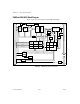
Figure A-9. BNC DACPads Single-Ended Connections
When you set the source type to the GS position and software-configure the
device for single-ended input, each BNC connector provides access to
two single-ended channels, AI x and AI x+8. For example, the BNC
connector labeled AI 0 provides access to single-ended channels AI 0 and
AI 8, the BNC connector labeled AI 1 provides access to single-ended
channels AI 1 and AI 9, and so on. Up to 16 single-ended channels are
available in single-ended measurement modes.
For a detailed description of each signal, refer to the I/O Connector Signal
Descriptions section of Chapter 1, DAQ System Overview.
AI
x
+
AI
x
–
GS
0.1 µF
5 kΩ
AI GND
FS
AI
x
+ 8
AI
x
GS
0.1 µF
5 kΩ
AI GND
FS