
User manual


Chapter 3 Analog Output
E Series User Manual 3-14 ni.com
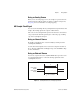
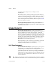
Figure 3-11 shows the timing requirements for the
ao/SampleClockTimebase signal.
Figure 3-11. ao/SampleClockTimebase Signal Timing Requirements
The maximum allowed frequency is 20 MHz, with a minimum pulse width
of 10 ns high or low. There is no minimum frequency.
Unless you select an external source, either the 20MHzTimebase or
100kHzTimebase generates the ao/SampleClockTimebase signal.
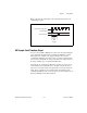
Master Timebase Signal
The Master Timebase (MasterTimebase) signal, or Onboard Clock, is the
timebase from which all other internally generated clocks and timebases on
the board are derived. It controls the timing for the analog input, analog
output, and counter subsystems. It is available as an output on the I/O
connector, but you must use one or more counters to do so.
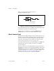
The maximum allowed frequency for the MasterTimebase is 20 MHz, with
a minimum pulse width of 23 ns high or low. There is no minimum
frequency limitation.
The two possible sources for the MasterTimebase signal are the internal
20MHzTimebase signal or an external signal through RTSI 7. Typically the
20MHzTimebase signal is used as the MasterTimebase unless you wish to
synchronize multiple devices, in which case, you should use RTSI 7. Refer
to Chapter 8, Real-Time System Integration Bus (RTSI), for more
information about which signals are available through RTSI.
t
p
= 50 ns minimum
t
w
= 23 ns minimum
t
w
t
w
t
p