
Programming instructions


Chapter 2 Lab and 1200 Devices
©
National Instruments Corporation 2-7 DAQ Hardware Overview Guide
Lab and 1200 Devices Interval Counter/Timer Operation
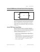
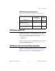
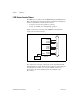
Figure 2-1 diagrams the available 16-bit counters.
Figure 2-1.
Lab and 1200 Device Interval Counter Block Diagram
Each counter has a clock input, a gate input, and an output. You can use a
counter to count the falling edges of the signal applied to the CLK input.
The Lab and 1200 devices use the counter gate input to gate counting
operations. Refer to the counter data sheet included in your device user
manual to see how the gate inputs affect the counting operation in different
counting modes.
Lab and 1200 Devices Counter/Timers
The Lab and 1200 devices contain two onboard 8253 Programmable
Interval Timer chips that have three independent 16-bit counter/timers. One
of these chips, the 8253-A, is reserved for data acquisition and waveform
generation operations. You can use the three counters on the other chip, the
8253-B, for counting/timing operations. NI-DAQ uses the three
counter/timers from the 8253-B as follows:
• Counter 0 is used for extending the timebase for data acquisition or
waveform generation when the interval between samples or updates is
greater than 65,535 µs.
• Counter 1 can be reserved for data acquisition using interval scanning
on all Lab and 1200 devices or Track*/Hold manipulation for the
SCXI-1140 with all Lab and 1200 devices except the DAQPad-1200.
Counter 1 is otherwise available for counting/timing operations.
• Counter 2 is always available.
GATE
CLOCK
Counter OUT