
Programming instructions


Chapter 7 PC-TIO-10 Timing I/O Device
DAQ Hardware Overview Guide 7-6 www.ni.com
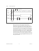
PC-TIO-10 Digital I/O
The PC-TIO-10 device contains 16 bits of digital I/O. These bits are
divided into a set of two digital I/O ports of eight bits each. The digital I/O
ports are labeled as ports A and B on the I/O connector as shown in the
PC-TIO-10 User Manual. These ports are referred to as ports 0 and 1 by the
Digital I/O functions in which:
• Port A = port 0
• Port B = port 1
Digital I/O on this device is controlled by the Motorola MC6821 Peripheral
Interface Adapter chip, the ports of which you can program on a bit-by-bit
basis—you can configure each bit individually for input or output. In
addition, any bit that you configure as an output bit has read-back
capability.
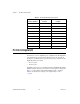
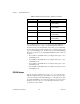
Table 7-1.
PC-TIO-10 Adjacent Counter Sequence
Counter Number
Upper Adjacent
Counter
Lower Adjacent
Counter
1 2 5
2 3 1
3 4 2
4 5 3
5 1 4
6 7 10
7 8 6
8 9 7
9 10 8
10 1 9