
Programming instructions


Chapter 11 AMUX-64T External Multiplexer Accessory
DAQ Hardware Overview Guide 11-2 www.ni.com
channel numbering of the second device can be from 64 through
127 (single-ended), or from 64 through 95 (differential). Therefore,
single-ended and differential channels always begin at the same number on
each device.
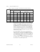
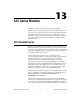
When you use more than one AMUX-64T accessory, address the channels
on the different devices, as shown in Table 11-2.
The channel address on each AMUX-64T depends on the switch setting on
each device. See the AMUX-64T User Manual for more information on the
external multiplexer device.
Scanning Order Using the AMUX-64T
The scanning counters on the AMUX-64T and on the MIO or AI accessory
perform automatic scanning of the AMUX-64T analog input channels.
When you perform a multiple-channel scanned data acquisition with
an AMUX-64T, one of the counter/timers on the MIO or AI device
normally available to you. Counter 1, is used for switching the MIO
or AI device onboard multiplexers.
Scanning is a simple operation for one AMUX-64T device but becomes
more complex for multiple AMUX-64T accessories. The following
paragraphs explain in detail how channels are scanned from the
AMUX-64T. You must know this scanning order so that you can determine
from which analog input channel the data was scanned during a data
acquisition operation. When a single AMUX-64T accessory is connected
to the MIO or AI device, you must scan four AMUX-64T input channels
for every MIO or AI device channel. If two AMUX-64T accessories are
attached to the MIO or AI device, you must scan eight AMUX-64T
channels for every MIO or AI device input channel. For example, channels
0 through 3 on AMUX-64T accessory A and channels 64 through 67 on
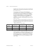
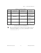
Table 11-2.
AMUX-64T Channel Numbers
AMUX-64T
Device
Channel Number
Single-Ended Differential
Device A 0–63 0–31
Device B 64–127 64–95
Device C 128–191 128–159
Device D 192–255 192–223