
Programming instructions


Chapter 11 AMUX-64T External Multiplexer Accessory
DAQ Hardware Overview Guide 11-4 www.ni.com
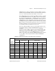
For example, if you use one AMUX-64T accessory, whenever NI-DAQ
selects channel 0 on the MIO or AI device in the scan sequence, channels
0 through 3 on the AMUX-64T are automatically scanned. If you use
two AMUX-64T accessories, channels 0 through 3 (accessory A) and
channels 64 through 67 (accessory B) are automatically scanned whenever
channel 0 is selected in the scan sequence. If you use four AMUX-64T
accessories, channels 0 through 3 (accessory A), channels 64 through 67
(accessory B), channels 128 through 131 (accessory C), and channels 192
through 195 (accessory D) are automatically scanned whenever channel 0
is selected in the scan sequence.
If you program the MIO or AI device with a sequential channel scan
sequence of 0 through 7 or 0 through 15, the AMUX-64T channels are
scanned from top to bottom in the order given in Table 10-3. Notice that if
you use differential input configuration, you should enter only MIO or AI
device channels 0 through 7 in the scan sequence in the NI-DAQ function
SCAN_Setup or the LabVIEW AI_Config.vi or
AI_Group_Config.vi, in which case only the information pertaining to
those channels in Table 11-3 applies. See the AMUX-64T User Manual for
more information on the external multiplexer device.
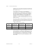
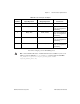
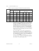
9 36–39 36–39 100–103 36–39 100–103 164–167 228–231
10 40–43 40–43 104–107 40–43 104–107 168–171 232–235
11 44–47 44–47 108–111 44–47 108–111 172–175 236–239
12 48–51 48–51 112–115 48–51 112–115 176–179 240–243
13 52–55 52–55 116–119 52–55 116–119 180–183 244–247
14 56–59 56–59 120–123 56–59 120–123 184–187 248–251
15 60–63 60–63 124–127 60–63 124–127 188–191 252–255
Table 11-3. AMUX-64T Scanning Order for Each MIO or AI Device Input Channel (Continued)
MIO
or AI Device
Channel
AMUX-64T Channels
One
Accessory
Two Accessories Four Accessories
Accessory
A
Accessory
A
Accessory
B
Accessory
A
Accessory
B
Accessory
C
Accessory
D