
Programming instructions

Chapter 7 Buffering Your Way through Waveform Acquisition
©
National Instruments Corporation 7-13 LabVIEW Data Acquisition Basics Manual
AI Read VI repeatedly to retrieve your data. These changes can be applied
to many of the examples in the previous section on simple buffered analog
input, however we will review the basic circular-buffered analog input VI
here, and describe some other example VIs that are included with
LabVIEW.
Basic Circular-Buffered Analog Input
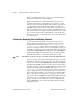
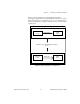
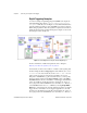
Figure 7-12 shows an example VI that brings data from channel 0 at a rate
of 1,000 samples/s into a buffer that can hold 4,000 samples. This type of
example might be handy if you wanted to watch the data from a channel
over a long period of time, but you could not store all the data in memory
at once. The AI Config VI sets up the channel specification and buffer size,
then the AI Start VI initiates the background data acquisition and specifies
the rate. Inside the While Loop, the AI Read VI repeatedly reads blocks of
data from the buffer of a size equal to either 1,000 scans or the size of the
scan backlog
—whichever one is larger. The VI does this by using the
Max & Min function to determine the larger of the two values. You do not
have to use the Max & Min function in this way for the application to work,
but the function helps control the size of the
scan backlog
, which is how
many samples that are left over in the buffer. This VI continuously reads
and displays the data from channel 0 until an error occurs or until you press
the
Stop
button.
Figure 7-12.
Basic Circular-Buffered Analog Input Using the Intermediate VIs
Other Circular-Buffered Analog Input Examples
There are many other circular-buffered analog input VIs that are included
with your LabVIEW application. The following sections briefly explain
some of these VIs. You can find the first two VIs in
labview\examples\