
Programming instructions

Chapter 8 Controlling Your Acquisition with Triggers
LabVIEW Data Acquisition Basics Manual 8-2
©
National Instruments Corporation
Digital Triggering
A
digital trigger
is usually a transistor-transistor logic (TTL) level signal
having two discrete levels—a high and a low level. When moving from
high to low or low to high, a digital edge is created. There are two types of
edges: rising and falling. You can set your analog acquisition to start as a
result of the rising or falling edge of your digital trigger signal.
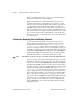
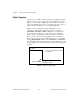
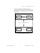
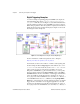
In Figure 8-1, the acquisition begins after the falling edge of the
digital trigger signal. Usually digital trigger signals are connected to
STARTTRIG*, EXTTRIG*, DTRIG, or PFI pins on your DAQ device.
If you want to know which pin your device has, check your hardware
manual, or refer to the AI Trigger Config VI description in Chapter 18,
Advanced Analog Input VIs
, of the
LabVIEW Function and VI Reference
Manual
. You also can refer to the LabVIEW
Online Reference
, available by
selecting
Help»Online Reference…
.The STARTTRIG* and EXTTRIG*
pins, which have and asterisk after their names, regard a falling edge signal
as a trigger. Make sure you account for this when specifying your triggering
conditions.
Figure 8-1.
Diagram of a Digital Trigger
TTL Signal
Connect to STARTTRIG*, EXTTRIG*,
or DTRIG Pins
Falling Edge of Signal
Data Capture Initiated