
Programming instructions

Chapter 9 Letting an Outside Source Control Your Acquisition Rate
©
National Instruments Corporation 9-3 LabVIEW Data Acquisition Basics Manual
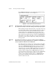
You can set your channel clock rate with the
interchannel delay
input of
the AI Config VI, which calls the Advanced AI Clock Config VI to actually
configure the channel clock. The simplest method to select an interchannel
delay is to gradually increase the delay, or clock period, until the data
appears consistent with data from the previous delay setting.
Refer to your hardware manuals for the required settling time for your
channel clock. You can also find the interchannel delay by running the
low-level AI Clock Config VI for the channel clock with no frequency
specified.
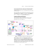
Externally Controlling Your Channel Clock
There are times when you might need to control the channel clock
externally. The channel clock rate is the same rate at which analog
conversions occur. For instance, suppose you need to know the strain value
at an input, every time an infrared sensor sends a pulse. Most DAQ devices
have an EXTCONV* pin or a PFI pin on the I/O connector for providing
your own channel clock. This external signal must be a TTL level signal.
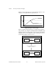
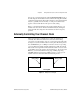
The asterisk on the signal name indicates that the actual conversion occurs
on the falling edge of the signal, as shown in Figure 9-3. For devices with
PFI lines, you can select either the rising edge of falling edge using
LabVIEW. With devices that have a RTSI connector, you can get your
channel clock from other National Instruments DAQ devices.
Figure 9-3.
Example of a TTL Signal
TTL Signal
rising edge
falling edge