
Programming instructions

Chapter 9 Letting an Outside Source Control Your Acquisition Rate
©
National Instruments Corporation 9-5 LabVIEW Data Acquisition Basics Manual
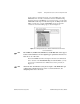
On most devices, external conversions occur on the falling edge of the
EXTCONV* line. Consult your hardware reference manual for timing
diagrams. On devices with PFI lines (e.g., E-series devices), you can set the
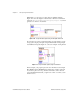
Clock Source Code
input of AI Clock Config VI to the PFI pin with either
falling or rising edge or use the default PFI2/Convert* pin where the
conversions occur on the falling edge, as shown in Figure 9-5.
Figure 9-5.
Setting the Clock Source Code for External Conversion Pulses
for E-Series Devices
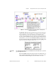
Note
The AT-MIO-16, AT-MIO-16D, NB-MIO-16, and NB-MIO-16X cannot support
both an external channel clock and a digital trigger signal at the same time. You
must choose one or the other.
Because LabVIEW determines the length of time before the AI Read VI
times out based on the
interchannel delay
and
scan clock rate
, you may
need to force a time limit for the AI Read VI, as shown previously in
Figure 9-4.
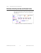
Note
On the Lab-PC+ and 1200 devices, the first clock pulse on the EXTCONV* pin
configures the acquisition but does not cause a conversion. However, all
subsequent pulses cause conversions.