
Programming instructions

Chapter 9 Letting an Outside Source Control Your Acquisition Rate
LabVIEW Data Acquisition Basics Manual 9-6
©
National Instruments Corporation
Externally Controlling Your Scan Clock
External scan clock control may be more useful than external channel clock
control if you are sampling multiple channels, but may not be as obvious to
find because it does not have the input on the I/O connector labeled
ExtScanClock
, the way the EXTCONV* pin does.
Note
Some MIO devices have an output on the I/O connector labeled SCANCLK.
This cannot be used as an input.
The appropriate pin to input your external scan clock can be found in the
Table 9-1.
Note
Some devices do not have internal scan clocks and therefore do not support
external scan clocks. These devices include, but are not limited to the following:
NB-MIO-16, PC-LPM-16, PC-LPM-16PnP, PC-516, DAQCard-500,
DAQCard-516, DAQCard-700, Lab-NB, Lab-SE, and Lab-LC.
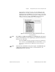
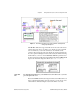
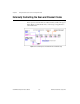
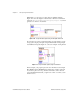
After connecting your external scan clock to the correct pin, set up
the external scan clock in software. In Figure 9-6, the example
Acquire N Scans-ExtScanClk VI located in
labview\examples\daq\
anlogin\anlogin.llb
shows how to do this. Two advanced VIs,
AI Clock Config and AI Control, are used in place of the intermediate
AI Start VI. This allows access to the
clock source
input. This is necessary
because it allows access to the
clock source string
which is used to identify
the PFI pin to be used for the scan clock for E-series boards. The
clock
source
also includes the
clock source code
(on the front panel) which is set
to I/O connector. The 0 wired to the Clock Config VI disables the internal
clock.
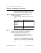
Table 9-1.
External Scan Clock Input Pins
Device External Scan Clock Input Pin
AT-MIO-16
AT-MIO-16F-5
AT-MIO-16X
AT-MIO-16D
AT-MIO-64F-5
OUT2
All E-Series Devices Any PFI Pin
Lab-PC+
1200 devices
OUT B1