
Programming instructions

Chapter 12 Buffering Your Way through Waveform Generation
LabVIEW Data Acquisition Basics Manual 12-4
©
National Instruments Corporation
Changing the Waveform during
Generation: Circular-Buffered Output
When the waveform data is too large to fit in a memory buffer or is
constantly changing, use a
circular buffer
to output the data. You also can
use the Easy Analog Output VIs in a loop to create a circular-buffered
output; but this sacrifices efficiency because Easy VIs configure, allocate,
and deallocate a buffer every time they execute, which causes time gaps
between the data output. Figures 12-4 and 12-5 show two different ways to
perform circular-buffered analog output using the Intermediate VIs in
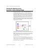
LabVIEW. Figure 12-4 shows the AO Continuous Gen VI, which is more
efficient than the Easy Analog Output VIs in that it configures and allocates
a buffer when its
iteration
input is 0 and deallocates the buffer when the
clear generation
input is TRUE.
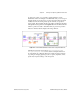
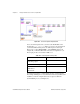
Figure 12-4.
Circular Buffered Waveform Generation Using the AO Continuous Gen VI
With the AO Continuous Gen VI, you can configure the size of the data
buffer and the limit settings of each channel. For more information on how
to set limit settings, refer to Chapter 3, Basic LabVIEW Data
Acquisition Concepts.
The Continuous Generation example VI, located in
labview\examples\
daq\anlogout\anlogout.llb
, uses the AO Continuous Gen VI. In this
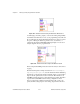
example, the data completely fills the buffer on the first iteration. On
subsequent iterations, new data is written into one half of the buffer while
the other half continues to output data.