
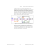
Programming instructions

Chapter 13 Letting an Outside Source Control Your Update Rate
LabVIEW Data Acquisition Basics Manual 13-2
©
National Instruments Corporation
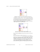
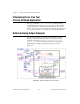
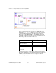
Figure 13-1.
Generate N Updates-ExtUpdateClk VI
To use an external update clock, you must set the
clock source
of the
AO Start VI to
I/O connector
. When you connect your external clock,
you find that different DAQ devices use different pins for this input.
However, if you select
Show VI Info…
in the
Windows
menu of the
example VI, you find that all the I/O connections are explained for you.
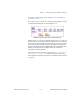
These input pins also are described in Table 13-1.
For waveform generation, you must supply an array of waveform data.
The example VI in Figure 13-1 uses data created in the Compute Waveform
VI. When you run the example VI, the data is output on channel 0
(the DAC0OUT pin) of your DAQ device.
Table 13-1.
External Update Clock Input Pins
Device Input External Update Clock Pin
All E-Series Devices
with analog output
PFI5/UPDATE*
Non E-Series MIO type devices OUT2
Lab-PC+
1200 devices
AT-AO -6/10
EXTUPDATE*