
Programming instructions

Chapter 14 Simultaneous Buffered Waveform Acquisition and Generation
LabVIEW Data Acquisition Basics Manual 14-2
©
National Instruments Corporation
Software Triggered
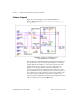
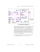
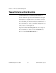
Figure 14-1 shows the diagram of the Simul AI/AO Buffered
(E-series MIO) VI located in
labview\examples\daq\anlog_io\
anlog_io.llb
.
Figure 14-1.
Simultaneous Input/Output Using the
Simul AI/AO Buffered (E-series MIO) VI
This example VI uses familiar Intermediate DAQ VIs. This example VI
uses the same VIs you used for analog input in Chapter 7—AI Config,
AI Start, AI Read, and AI Clear—for waveform acquisition here. This
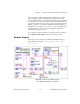
example VI also uses the same VIs you used for analog output in
Chapter 12—AO Config, AO Write, AO Start, and AO Clear—for
waveform generation here. By following the
error
cluster wire, which
enters each DAQ VI on the bottom left and exits on the bottom right, you
can see that because of data dependency, the waveform generation starts
before the waveform acquisition, and each task is configured to run
continuously. This example VI is considered software triggered because it
starts via software when you push the
Run
button.