
Programming instructions

Chapter 14 Simultaneous Buffered Waveform Acquisition and Generation
LabVIEW Data Acquisition Basics Manual 14-4
©
National Instruments Corporation
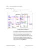
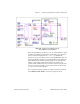
Although this VI is similar to the example in Figure 14-1, it is more
advanced because it uses a hardware trigger. The waveform acquisition
trigger is set up with the
trigger type
input to the AI Start VI set to
digital A
(start), and by default this trigger is expected on the PFI0 pin.
Hardware triggering for waveform generation requires an additional VI.
The AO Trigger and Gate Config VI is an advanced analog output VI for
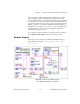
E-series boards only. The trigger parameters are set using three inputs. The
trigger or gate source
is used to choose the source of your trigger, such
as a PFI pin or a RTSI pin. The
trigger or gate source specification
is
used in conjunction with the
trigger or gate source
to choose which PFI
or RTSI pin number to use, such as 0 through 9 for a PFI pin. The
trigger or gate condition
is used to select a rising or falling trigger edge.
The default analog output trigger for this example is a rising edge on PFI0.
Because this is the same pin as the analog input trigger, the waveform
acquisition and generation starts simultaneously. However, they are not
controlled by independent counter/timers, so you can run them at different
rates.
For a complete description, instructions, and I/O connections for this VI,
select
Windows»Show VI Info…
from the front panel of the VI.
Using Legacy MIO Boards
Legacy MIO devices, such as the AT-MIO-16, have a total of five counters,
of which two or more can be used for data acquisition and generation.
However, certain counters are dedicated to certain tasks, and you must be
aware of this as you design your system.
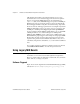
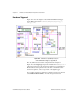
Software Triggered
Figure 14-3 shows the diagram of the Simul AI/AO Buffered (legacy MIO)
VI located in
labview\examples\daq\anlog_io\anlog_io.llb
.