
Programming instructions

©
National Instruments Corporation 15-1 LabVIEW Data Acquisition Basics Manual
15
Things You Should Know
about Digital I/O
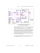
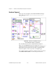
Digital I/O interfaces are often used to control processes, generate patterns
for testing, and communicate with peripheral equipment like heaters,
motors, and lights. Digital I/O components on DAQ devices and
SCXI modules consist of hardware parts that generate or accept binary
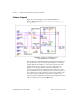
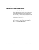
on/off signals. As shown in the diagram below, all digital lines are grouped
into ports on DAQ devices and banks on SCXI modules. The number of
digital lines per port or bank is specific to the particular device or module
used, but most ports or banks consist of four or eight lines. Except for the
TIO-10 and E-Series devices, all lines within the same port or bank must all
be of the same direction (either input or output), as shown in Figure 15-1.
By writing to or reading from a port, you can set or retrieve simultaneously
the states of multiple digital lines. Refer to Appendix B,
Hardware
Capabilities
, of the
LabVIEW Function and VI Reference Manual
, your
hardware user manual, or refer to the LabVIEW
Online Reference
, by
selecting
Help»Online Reference…
, for port information on your device.
Figure 15-1.
Digital Ports and Lines
Data latches
and drivers
Data latches
and drivers
Device or Module
Output Port
Input Port
Output Lines
Input Lines