
Programming instructions


Chapter 21 Common SCXI Applications
LabVIEW Data Acquisition Basics Manual 21-10
©
National Instruments Corporation
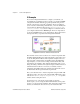
If you are measuring temperature with the SCXI-1120 and SCXI-1121
modules, refer to the example VI, SCXI-1120/1121 Thermocouple, located
in
labview\examples\daq\scxi\scxi_ai.llb
. This VI is similar to
the VI used to measure temperature on the SCXI-1100. Both VIs average
and linearize temperature data using the Intermediate analog input VIs. The
two main differences between the VIs are that the SCXI-1120/1121 VI does
not measure the amplifier offset, and the input limits for the module and the
temperature sensor are different from the input limits for the SCXI-1100.
The SCXI-1120 and SCXI-1121 modules do not have the internal switch
used to programmatically ground the amplifiers as in the SCXI-1100 for
the amplifier offset measurement. If you want to determine the amplifier
offset, you have to manually wire the amplifier terminals to ground and
use a separate VI to read the offset voltage. You can also manually
calibrate the SCXI-1120 and SCXI-1121 to remove any amplifier offset
on a channel-by-channel basis. Refer to the SCXI-1120 or SCXI-1121
user manuals for specific instructions.
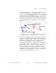
Measuring Temperature with RTDs
Resistance-Temperature Detectors (RTDs) are temperature-sensing
devices whose resistance increase with temperature. They are known for
their accuracy over a wide temperature range. RTDs require current
excitation to produce a measurable voltage. RTDs are available in 2-wire,
3-wire, or 4-wire configuration. The lead wires in the 4-wire configuration
are resistance-matched. If you use a 2-wire or 3-wire RTD, they are
unmatched. Resistance in the lead wires that connect your RTD to the
measuring system will add error to your readings. If you are using lead
lengths greater than 10-feet, you will need to compensate for this lead
resistance. RTDs are also classified by the type of metal they use. The most
common metal is platinum.
For more information about how the lead wires affect
RTD measurements as well as general RTD information, refer to the
Measuring Temperature with RTDs
application note. You can find this note
on the NI Fax-on-Demand system or by accessing the NI BBS, World Wide
Web, or FTP site, the numbers for which are in the front of this manual.
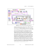
Signal conditioning is needed to interface an RTD to a DAQ device or an
SCXI-1200 module. Signal conditioning required for RTDs include current
excitation for the RTD, amplification of the measured signal, filtering of
the signal to remove unwanted noise, and isolation of the RTD and
monitored system from the host computer. Typically, you would use the
SCXI-1121 module with RTDs because it easily performs all the signal
conditioning listed previously. You must set up the excitation level, gain,