
Programming instructions

Chapter 23 Things You Should Know about Counters
LabVIEW Data Acquisition Basics Manual 23-2
©
National Instruments Corporation
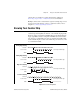
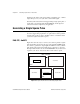
Knowing the Parts of Your Counter
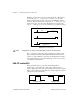
The following illustration shows a basic model of a counter.
A counter consists of a SOURCE or CLK input pin, a GATE input pin, an
OUT output pin, and a count register. In plug-in device diagrams and in the
LabVIEW Function Reference and VI Reference Manual, these counter
parts are called SOURCE
n
(or CLK
n
), GATE
n
, and OUT
n
, where
n
is the
number of the counter.
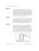
The parts of a counter work together as follows. Signal transitions (edges)
are counted at the SOURCE input. The count register can be preloaded with
a count value, and then for each counted edge, the counter increments or
decrements the count register. The count register value always reflects the
current count of signal edges. Reading the count register does not change
its value. The GATE input can be used to control when counting occurs in
your application. You can also use a counter with no gating, allowing the
software to initiate the counting operation.
The OUT pin can be toggled according to available counter programming
modes to generate various TTL pulses and pulse trains.
Use the OUT signal of a counter to generate various TTL pulse waveforms.
If you are incrementing the count register value, you can configure the
OUTsignal to either toggle signal states or pulse when the count register
reaches a certain value. The highest value of a counter is called the
terminalcount
(TC). If you are decrementing, the count register TC value
will be 0. If you chose to have pulsed output, then the counter outputs a high
pulse that is equal in time to one cycle of the counter’s SOURCE signal,
which can be either an internal or external signal. If you chose to have a
toggled output, the state of the output signal changes from high to low or
low to high. If you want more control over the length of high and low
GATE
SOURCE
(CLK)
OUT
Count Register