
Programming instructions

Chapter 23 Things You Should Know about Counters
LabVIEW Data Acquisition Basics Manual 23-4
©
National Instruments Corporation
DAQ-STC
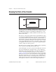
You can configure the DAQ-STC to count either low-to-high or
high-to-low transitions of the SOURCE input. The counter has a 24-bit
count register with a counting range of 0 to 2
24
-1. It can be configured to
increment or decrement for each counted edge. Furthermore, whether the
count register increments or decrements can be controlled with an external
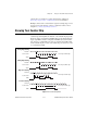
digital line which is useful for encoder applications. Of the gating modes
shown in Figure 23-1, the gating modes the DAQ-STC supports depends
upon the application. You can set the configuration parameters discussed
above using the Advanced VI, CTR Mode Config.vi.
Am9513
You can configure the Am9513 to count either low-to-high or high-to-low
transitions of the SOURCE input. The counter has a 16-bit count register
with a counting range of 0 to 65535, and can be configured to increment or
decrement for each counted edge. The Am9513 supports all of the gating
modes shown in Figure 23-1. You can set the configuration parameters
discussed above using the Advanced VI, CTR Mode Config.vi.
8253/54
The 8253/54 chip counts low-to-high transitions of the CLK input. The
counter has a 16-bit count register with a counting range of 65535 to 0
that decrements for each counted edge. Of the gating modes shown in
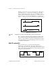
Figure 23-1, the 8253/54 supports only High Level Gating. For single pulse
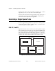
output, the 8253/54 can only create negative polarity pulses. For this
reason, some applications require the use of a 7404 inverter chip to produce
a positive pulse. The 14-pin 7404 is a common chip available from many
electronics stores, and can be powered with the 5 volts available on most
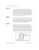
DAQ boards. Figure 23-2 shows how to wire a 7404 chip to invert a signal.
Figure 23-2.
Wiring a 7404 Chip to Invert a TTL Signal