
Programming instructions

©
National Instruments Corporation 24-1 LabVIEW Data Acquisition Basics Manual
24
Generating a Square Pulse
or Pulse Trains
This chapter describes the ways you can generate a square pulse or multiple
pulses (called
pulse trains
) using the counters available on your data
acquisition (DAQ) device with the example VIs in LabVIEW.
Generating a Square Pulse
There are many applications where you may need to generate TTL pulses.
TTL pulses can be used as clock signals, gates, and triggers. You can use a
pulse train of known frequency to determine an unknown TTL pulse width.
You also can use a single pulse of known duration to determine an
unknown TTL signal frequency, or use a single pulse to trigger an analog
acquisition.
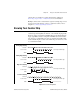
There are two basic types of counter signal generation—
toggled
and
pulsed
. When a counter reaches a certain value, a counter configured for
toggled output changes the state of the output signal, while a counter
configured for pulsed output outputs a single pulse. The width of the pulse
is equal to one cycle of the counter’s SOURCE signal.
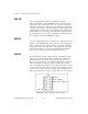
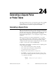
The following is a list of terms you should know before outputting a pulse
or pulse train using LabVIEW.
•
phase 1
refers to the first phase or delay to the pulse.
•
phase 2
refers to the second phase or the pulse itself.
•
period
is the sum of
phase 1
and
phase 2
.
• Frequency is the reciprocal of the
period
(1/
period
).
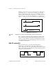
• In LabVIEW, you can adjust and control the times of
phase 1
and
phase 2
in your counting operation. You do this by specifying a
duty
cycle
. The duty cycle equals:
phase
2
period
---------------------
where
period, phase 1 phase 2
+=