
Programming instructions

Chapter 24 Generating a Square Pulse or Pulse Trains
LabVIEW Data Acquisition Basics Manual 24-2
©
National Instruments Corporation
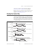
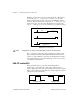
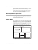
Examples of various duty cycles are shown in Figure 24-1. The first line
shows a duty cycle of
0.5
, where,
phase 1
and
phase 2
are the same
duration. A signal with a 0.5 duty cycle acts as a SOURCE for counter
operations. The second line shows a duty cycle of
0.1
, where
phase 1
has
increased and
phase 2
has decreased. The final line shows a large duty
cycle of
0.9
where
phase 1
is very short and the
phase 2
duration is longer.
Figure 24-1.
Pulse Duty Cycles
Note
A high duty cycle denotes a long pulse phase relative to the delay phase.
How you generate a square pulse varies depending upon which counter
chip your DAQ hardware has. Most National Instruments DAQ devices
contain one of three different counter chips: the DAQ-STC, the Am9513,
or the 8253/54 chip. If you are unsure which chip your device uses, refer to
your hardware documentation.
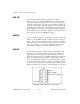
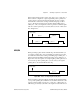
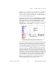
DAQ-STC and Am9513
When generating a pulse or pulse train with the DAQ-STC or
Am9513 chip, you can define the polarity of the signal as positive or
negative. Figure 24-2 shows these pulse polarities. Notice that for a signal
with a positive polarity, the initial state is low, while a signal with negative
polarity has a positive initial state.
Figure 24-2.
Positive and Negative Pulse Polarity
counter starts
phase 1
phase 2
Duty Cycle = 0.5
Duty Cycle = 0.1
Duty Cycle = 0.9
Positive Polarity Negative Polarity