
Programming instructions

Chapter 24 Generating a Square Pulse or Pulse Trains
©
National Instruments Corporation 24-3 LabVIEW Data Acquisition Basics Manual
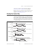
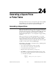
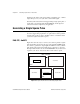
Each counter-generated pulse consists of two parts—
phase 1
and
phase 2
.
If the counter is configured to output a signal with positive polarity and
toggled output, as shown in the following diagram, the period of time
from when the counter starts counting to the first rising edge is called
phase 1
. The time between the rising and the following falling edge is
called
phase 2
. If you configure the counter to generate a continuous pulse
train, the counter repeats this process many times as shown on the bottom
line of Figure 24-3.
Figure 24-3.
Pulses Created with Positive Polarity and Toggled Output
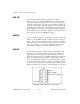
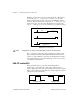
8253/54
When generating a pulse with the 8253/54 chip, the hardware limits you
to a negative polarity pulse, as shown in Figure 24-2. The period of time
from when the counter starts counting to the falling edge is called
phase 1
.
The time between the falling and following rising edge is called
phase 2
.
Figure 24-4 shows these phases for a single negative polarity pulse. If you
need to create a positive polarity pulse, you can connect your negative
polarity pulse to an external 7404 inverter chip.
Figure 24-4.
Phases of a Single Negative Polarity Pulse
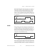
When generating a pulse train with the 8253/54 chip, the hardware limits
you to positive polarity pulses. Furthermore, the value loaded in the count
register is divided equally to create
phase 1
and
phase 2
. This means you
will always get a 0.5 duty cycle if the count register is loaded with an even
counter starts
phase 1
phase 2
phase 1 phase 2phase 1 phase 2
Single Pulse
Pulse Train
counter starts
phase 1
phase 2