
Programming instructions

Chapter 24 Generating a Square Pulse or Pulse Trains
©
National Instruments Corporation 24-5 LabVIEW Data Acquisition Basics Manual
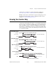
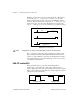
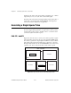
Figure 24-6 shows the diagram of the Delayed Pulse-Easy (DAQ-STC) VI
located in
labview\examples\daq\counter\DAQ-STC.llb
. You
could also use the example Delayed Pulse-Easy (9513) VI located in
labview\examples\daq\counter\Am9513.llb
. These examples use
the Easy level Generate Delayed Pulse VI.
The Generate Delayed Pulse VI, found in
Functions»Data Acquisition»
Counter
, tells your device to generate a single delayed pulse. This VI is
self-contained and checks for errors automatically. With the Generate
Delayed Pulse VI, you must connect the
pulse delay
(
phase 1
) and
pulse width
(
phase 2
) controls to define the output pulse. Sometimes the
actual pulse delay
and
pulse width
are not the same as you specified.
Figure 24-6.
Diagram of Delayed Pulse-Easy (DAQ-STC) VI
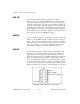
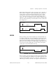
If you need more control over when the counter begins generating a single
square pulse, use Intermediate VIs instead of the Easy VIs. Figure 24-7
shows the diagram of the Delayed Pulse-Int (DAQ-STC) VI located in
labview\examples\daq\counter\DAQ-STC.llb
. You can also use
the example Delayed Pulse-Int (9513) VI located in
labview\examples\
daq\counter\Am9513.llb
. These examples show how to generate a
single pulse using Intermediate level VIs. The Delayed Pulse Generator
Config VI configures the counter and the Counter Start VI generates the
TTL signal. An example of this is generating a pulse as a result of meeting
certain conditions. If you used the Easy Counter VI, the VI configures and
then immediately starts the pulse generation. With the Intermediate VIs,
you can configure the counter long before the actual pulse generation
begins. As soon as you want a pulse to be generated, the counter can
immediately begin without having to configure the counter. In this
situation, using Intermediate VIs improves performance.