
Programming instructions

Chapter 24 Generating a Square Pulse or Pulse Trains
LabVIEW Data Acquisition Basics Manual 24-6
©
National Instruments Corporation
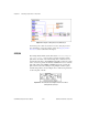
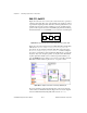
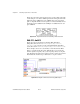
Figure 24-7.
Diagram of Delayed Pulse-Int (DAQ-STC) VI
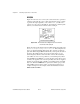
You must stop the counter if you want to use it for other purposes. For
more information on stopping counters, refer to the
Stopping Counter
Generations
section at the end of this chapter.
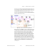
8253/54
The example Delayed Pulse (8253) VI located in
labview\examples\
daq\counter\8253.llb
shows how to generate a negative polarity
pulse. Due to the nature of the 8253/54 chip, three counters are used to
generate this pulse. Since only
Counter 0
is internally connected to a clock
source, it is used to generate the timebase.
Counter 1
is used to create the
pulse delay which gates
Counter 2
.
Counter 2
is used to generate the
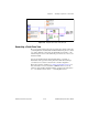
pulse, which occurs on the OUT pin. Using multiple counters requires
external wiring which is shown in Figure 24-8 as well as being described
on the front panel of the VI.
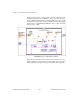
Figure 24-8.
External Connections Diagram from the Front Panel
of Delayed Pulse (8253) VI