
Programming instructions

Chapter 24 Generating a Square Pulse or Pulse Trains
LabVIEW Data Acquisition Basics Manual 24-8
©
National Instruments Corporation
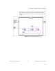
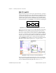
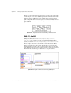
Figure 24-10 shows frame 1 of the sequence where the counters are set up
for different counting modes.
Counter 0
is set up to generate a timebase
using the ICTR Timebase Generator subVI.
Counter 1
is set up to toggle
its output (low-to-high) when it reaches terminal count (TC). This toggled
output is used to gate
Counter 2
.
Counter 2
is set up to output a low pulse
when its gate goes high.
Figure 24-10.
Frame 1 of Delayed Pulse (8253) VI
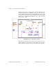
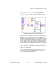
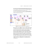
Figure 24-11 shows frame 2 of the sequence where a delay occurs so the
delayed pulse has time to complete before the example can be run again.
This is useful if the example is used as a subVI that is called repeatedly.