
Programming instructions

Chapter 24 Generating a Square Pulse or Pulse Trains
LabVIEW Data Acquisition Basics Manual 24-10
©
National Instruments Corporation
DAQ-STC, Am9513
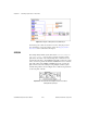
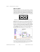
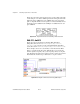
Figure 24-12 shows how to connect your counter and device to generate a
continuous pulse train. The edges of the internal source signal are counted
to generate the output signal. You obtain the continuous pulse train for your
external device from the counter’s OUT pin. You can optionally gate the
operation with a signal connected to the GATE input pin. Instead of having
an internal timebase as your SOURCE, you can connect an external signal.
Figure 24-12.
Physical Connections for Generating a Continuous Pulse Train
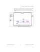
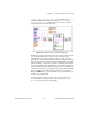
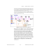
Figure 24-13 shows the diagram of the Cont Pulse Train-Easy (DAQ-STC)
VI located in
labview\examples\daq\counter\DAQ-STC.llb
.
You can also use the example Cont Pulse Train-Easy (9513) VI located
in
labview\examples\daq\counter\Am9513.llb
. These examples
show how to use the Easy Counter VI, Generate Pulse Train, to specify the
frequency, duty cycle, and pulse polarity of your pulse train. The number
of pulses parameter defaults to 0 for continuous generation. When you
press the
STOP
button, the while loop stops and a second call to Generate
Pulse Train with the number of pulses set to –1 stops the counter.
Figure 24-13.
Diagram of Cont Pulse Train-Easy (DAQ-STC) VI
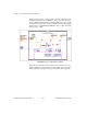
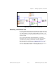
If you are generating a pulse train and want more control over when the
counter starts, use the Intermediate VIs. Figure 24-14 shows the diagram
of the Cont Pulse Train-Int (DAQ-STC) VI located in
labview\
counter
your
device
your
device
gate
source
out