
Programming instructions

Chapter 24 Generating a Square Pulse or Pulse Trains
©
National Instruments Corporation 24-15 LabVIEW Data Acquisition Basics Manual
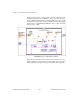
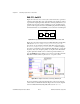
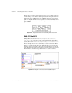
You can also create a finite pulse train using Intermediate VIs. Figure 24-19
shows the diagram of the Finite Pulse Train-Int (DAQ-STC) VI located in
labview\examples\daq\counter\DAQ-STC.llb
. You could also use
the example Finite Pulse Train-Int (9513) VI located in
labview\examples\daq\counter\Am9513.llb
. These examples
show how to use the Intermediate VIs Continuous Pulse Generator Config
and Delayed Pulse Generator Config.
Figure 24-19.
Diagram of Finite Pulse Train-Int (DAQ-STC) VI
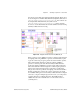
In this operation, you use
counter
to generate a continuous pulse train with
level gating while using
counter-1
to generate a minimum delayed pulse
to gate the counter long enough to generate the desired number of pulses.
The Continuous Pulse Generator Config VI configures
counter
to
generate a continuous pulse train. Then, the Delayed Pulse Generator
Config VI configures
counter-1
to generate a single delayed pulse. The
first Counter Start VI in the flow begins the continuous pulse generation
and the next Counter Start VI generates a pulse after a specified time.
The gate mode must be specified as level-gating on the Continuous Pulse
Generator Config VI in order for the counter to wait for the gate signal
from
counter-1
. The gate mode for the Delayed Pulse Generator Config VI
can be set to a single or multiple edges. In other words, you could produce
one finite pulse train or multiple pulse trains. The GATE signal for
counter-1
can be from an external device or from another counter on
your DAQ device.