
Programming instructions


Chapter 24 Generating a Square Pulse or Pulse Trains
LabVIEW Data Acquisition Basics Manual 24-16
©
National Instruments Corporation
DAQ-STC
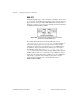
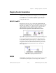
With the DAQ-STC chip, you have the ability to internally route the OUT
of one counter to the GATE of the next higher order counter, as shown in
Figure 24-20. You can optionally GATE
counter-1
. Notice that while you
still use two counters, you do not need to externally wire between the OUT
of
counter-1
and the GATE of
counter
.
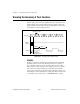
Figure 24-20.
External Connections Diagram from the Front Panel
of Finite Pulse Train Adv (DAQ-STC) VI
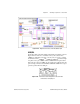
The example Finite Pulse Train-Adv (DAQ-STC) VI located in
labview\examples\daq\counter\DAQ-STC.llb
takes advantage of
this internal wiring. Figure 24-21 shows the diagram of this example,
which uses the Advanced counter VIs. The top row of
counter
VIs sets
up
counter
to output a pulse train. Notice that the gate source input to
the CTR Mode Config VI is set to
output of next lower order
counter
. This sets the internal wiring such that
counter
will be gated by
counter-1
. The bottom row of counter VIs sets up
counter-1
to output a
single pulse. The width of the pulse is calculated so it gates
counter
just
long enough to output the chosen number of pulses. For a complete
description of this example, refer to the information found in
Windows»Show VI Info…
.