
Programming instructions


Chapter 24 Generating a Square Pulse or Pulse Trains
©
National Instruments Corporation 24-17 LabVIEW Data Acquisition Basics Manual
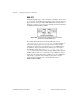
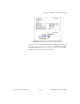
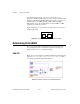
Figure 24-21.
Diagram of Finite Pulse Train-Adv (DAQ-STC) VI
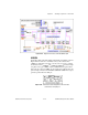
8253/54
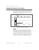
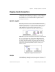
Generating a finite pulse train with the 8253/54 chip uses all three counters.
Figure 24-22 shows how to externally connect your counters. Since
counter 0
is internally connected to a clock source, it is used to generate
the timebase used by
counter 1
and
counter
2
.
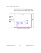
counter 1
generates a single
low pulse used to gate
counter 2
. Since
counter 2
must be gated with a
high pulse, the output of
counter 1
is passed through a 7404 inverter chip
prior to being connected to the GATE of
counter 2
.
counter 2
is set up to
generate a pulse train at its OUT pin.
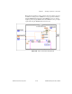
Figure 24-22.
External Connections Diagram from the Front Panel
of Finite Pulse Train (8253) VI