
Programming instructions


Chapter 24 Generating a Square Pulse or Pulse Trains
©
National Instruments Corporation 24-19 LabVIEW Data Acquisition Basics Manual
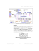
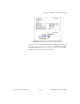
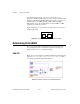
Figure 24-24 shows frame 1 of the sequence where the counters are set up
for different counting modes.
Counter 0
is set up to generate a timebase
using the ICTR Timebase Generator VI.
Counter 1
is set up to output a
single low pulse using the ICTR Control VI.
Counter 2
is set up to output
a pulse train using the ICTR Timebase Generator VI.
Figure 24-24.
Frame 1 of Finite Pulse Train (8253) VI